Hello! Welcome to Embedic!
ATmega8 is an 8-bit CMOS microcontroller of the AVR series (developed by Atmel Corporation in 1996), based on the RSIC (Reduced Instruction Set Computer) architecture, and its basic advantage is that it does not contain any accumulators, and the result of any operation can be stored in any register defined by the instruction.
The application of the ATmega8 AVR microcontroller is also very extensive, and it is still used as the basis for learning and researching advanced microprocessors. The ATmega8 block diagram is shown in the figure below:
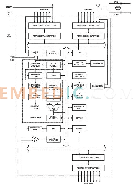
Memory:
It consists of 8KB of flash memory, 1KB of SRAM and 512 bytes of EEPROM. 8K Flash is divided into two parts - the lower part is used as the boot flash part, and the upper part is used as the application flash part. SRAM contains 1K bytes and 1120 bytes of general registers and I/O registers.
The lower 32 address locations are used for the 32 general-purpose 8-bit registers, and the next 64 addresses are used for the I/O registers. Additionally, all registers are directly connected to the ALU, and EEPROM is used to store user-defined data.
Input/output port
ATmega8 consists of 23 I/O lines and 3 I/O ports named B, C and D respectively.
The registers corresponding to any port X (B, C or D) are:
Timers and Counters
The ATmega8 consists of 3 timers with comparable modes, two of which are 8-bit and the third is 16-bit.
Oscillator
The ATmega8 includes an internal reset and oscillator which eliminates the need for any external inputs. An internal RC oscillator generates an internal clock that can be programmed to run at any frequency of 1MHz, 2MHz, 4MHz or 8MHz. In addition, it supports an external oscillator with a maximum frequency of 16MHz.
Communication
ATmega8 provides synchronous and asynchronous data transmission schemes through USART (Universal Synchronous and Asynchronous Receiver Transmitter), that is, to communicate with modems and other serial devices. It also supports SPI (Serial Peripheral Interface) for communication between devices in a master-slave manner, another type of communication supported is TWI (Two-Wire Interface), and allows any Commutation between two devices.
ATmega8 also has a comparator module integrated in the chip for comparison between two voltages connected to the two inputs of the analog comparator through an external chip.
It also contains a 6-channel ADC, 4 of which have 10-bit precision and 2 of which have 8-bit precision.
Status Register:
ATmega8 contains information about the currently executing arithmetic instruction set.
ATmega8 Pinout Configuration Diagram
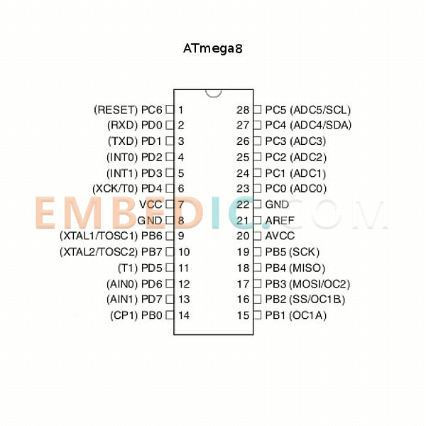
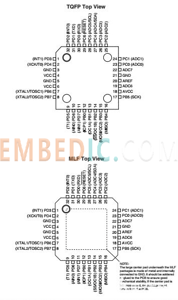
One of the distinguishing features of the ATmega8 is that all but five pins support two signals.
Pins 23, 24, 25, 26, 27, 28, and 1 are for port C, while pins 9, 10, 14, 15, 16, 17, 18, 19 are for port B, pins 2, 3, 4 , 5, 6, 11, 12 for port D.
Pin 1 is also the reset pin, if a low signal is applied for longer than the minimum pulse length, a reset will be generated.
Pins 2 and 3 are also used for serial communication of the USART.
Pins 4 and 5 are used as external interrupts, one of which is triggered when the interrupt flag bit in the status register is set, and the other is triggered when the interrupt condition is met.
Pins 9 and 10 are used as an external oscillator as well as a timer counter oscillator with a crystal connected directly between the pins. Pin 10 is used for crystal oscillator or low frequency crystal oscillator, if internally calibrated RC oscillator is used as clock source and asynchronous timer is enabled, these pins can be used as timer oscillator pins.
Pin 19 is used as master clock output and slave clock input for SPI channel.
Pin 18 is used as master clock input and slave clock output.
Pin 17 is used as master data output and slave data input for SPI channel. It is used as an input when enabled by a slave and is bidirectional when enabled by a master. This pin can also be used as an output compare match output for an external output of a timer/counter compare match.
Pin 16 is used as a slave select input and it can also be used as a timer/counter 1 compare match by configuring the PB2 pin as an output.
Pin 15 can be used as an external output for Timer/Counter Compare Match A.
Pins 23 to 28 are always used for ADC channels. Pin 27 can also be used as serial interface clock and pin 28 can be used as serial interface data.
Pins 13 and 12 are used as analog comparator inputs.
Pins 11 and 6 are used for timer/counter sources.
Sleep mode
The ATmega8 microcontroller operates in 5 sleep modes, namely:
Idle Mode: It stops the CPU from running, but allows SPI, USART, ADC, TWI, Timer/Counter and Watchdog to run and interrupt the system. It is implemented by setting the SM0 to SM2 bits of the MCU register flags to zero.
ADC Noise Reduction Mode: It stops the CPU but allows the ADC, external interrupt, Timer/Counter 2 and watchdog to run.
Power-down mode: It enables external interrupts, 2-wire serial interface, watchdog while disabling the external oscillator and stops all generated clocks.
Power saving mode: used when the timer/counter is clocked asynchronously, it stops all clocks except clkASY.
Standby Mode: In this mode, the oscillator is allowed to operate and all other operations are stopped.
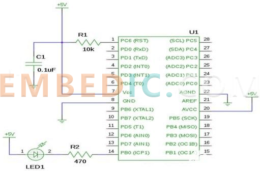
Main application
The image below is a blinking LED using an ATmega8 microcontroller. The program is written in C language and first compiled into a .c file. The ATMEL software tool will convert this file to a binary ELF object file, then convert it again to a hex file, and finally use the AVR dude program to pass the hex file to the microcontroller for processing.
Further Reading: Design and analysis of infrared remote control circuit based on Atmega8 microcontroller
Summary
The ATmega8 microcontroller is manufactured using Atmes high-density non-volatile memory technology, and the flash program memory can be reprogrammed in-system via the SPI serial interface, a traditional non-volatile memory programmer, or an on-chip bootloader running on the VR core.
The bootloader can use any interface to download the application into the application flash. While the application flash section is updated, the software in the boot flash section continues to run, demonstrating true read-while-write operation by combining an 8-bit RISC CPU with in-system self-programming flash memory on a monolithic chip.
The Atmel Atmega8 is a powerful microcontroller that provides a highly flexible and cost-effective solution for many embedded control applications. Atmega8 AVR supports a full set of program and system development tools, including C compiler, macro assembler, program deb simulator, in-circuit emulator and evaluation kit, etc.
Manufacturer: Texas Instruments
IC DSP FIXED-POINT 697FCBGA
Product Categories: DSP
Lifecycle:
RoHS:
Manufacturer: Texas Instruments
IC DSP FIX/FLOAT POINT 256BGA
Product Categories: DSP
Lifecycle:
RoHS:
Manufacturer: Texas Instruments
IC DSP FIX/FLOAT POINT 361NFBGA
Product Categories: DSP
Lifecycle:
RoHS:
Manufacturer: Texas Instruments
IC DSP FIX/FLOAT POINT 841FCBGA
Product Categories: DSP
Lifecycle:
RoHS:
Looking forward to your comment
Comment
1
2
3
4
5
6
 Popular Searches
8 Bit MCU, Flash, PIC16 Family PIC16F7XX Series Microcontrollers, 20 MHz, 7 KB, 192 Byte, 44 Pi...
EEPROM 2K 256 X 8 2.5V SERIAL EE IND
System-On-Modules - SOM RCM2200
32-bit Arm Cortex-A53 vision processor with ISP, powerful 3D GPU, dual APEX-2 vision accelerat...
IC MCU 8BIT 60KB FLASH 44QFP
DSP 20MHZ 44QFP
Product updates, events, and resources in your inbox


Smart System

Traffic Management

Security

Consumer Electronics

Wireless Technology

Robot

Internet of Things

Industrial Control


