Hello! Welcome to Embedic!
Simulation software: Proteus 8.9
Download, and install, pay attention to install in the root directory of C disk
In this paper, the software comes with Oven to achieve temperature feedback control.
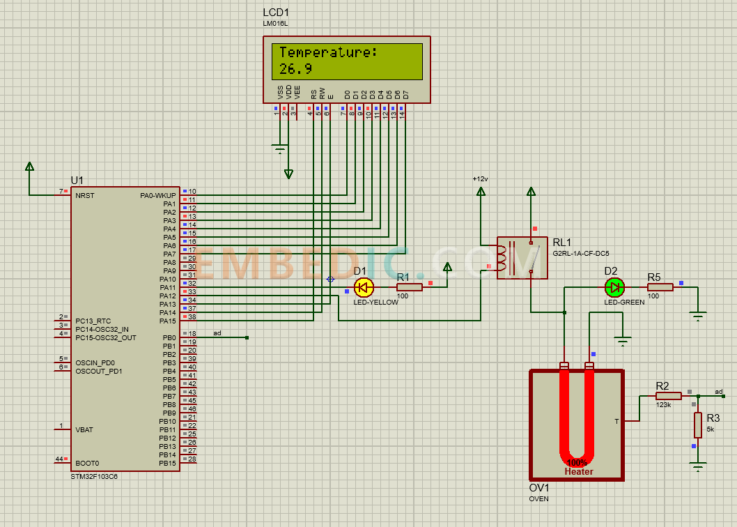
Add STM32F103C6 module, LM016L LCD module, a yellow LED, a green LED, two 100 ohm resistors, a relay switch, a pair of 123k and 5k voltage divider resistors, and the Oven module.
After adding, connect the wires as shown in the figure, pay attention to the setting of the ad network label
To learn more about STM32 products, please click stm32
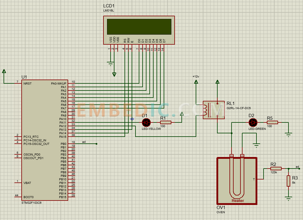
The temperature is obtained through the STM32's own ADC, compared with the set value, and then the power driver of the Oven is controlled through the IO port, thus achieving negative feedback. At the same time, the STM32 also needs to control the LCD information display.
Please download the program code first.
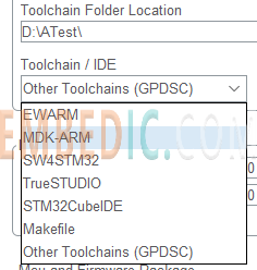
First use STM32CubeMX. Open ATest.ioc.
The previous configuration is done, jump to Project Manager and choose your favorite IDE for STM32 program development.
Open the project and start with the development of the display control. The code is available in the package, so here is only an excerpt
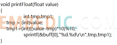
Because the program can not print floating point numbers for some reasons, here to do a floating point number printing
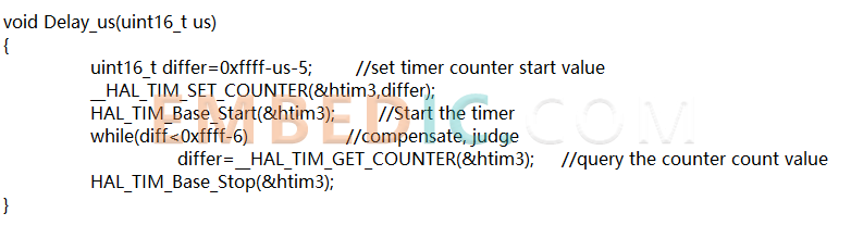
Here is the delay function

Here is the LCD control command function, in accordance with the LCD protocol will control the command to write the LCD screen
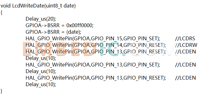
Here is the function of the LCD data command, when writing data, it will make the LCD display characters in the pointer position
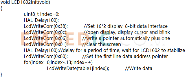
Here is the LCD initialization function, the first line will be written to "Temperature:"
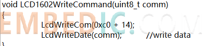
Here is the LCD command function
The following is the main function, all of their own code should be added in the corresponding USER CODE
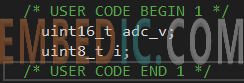
Initialization variables
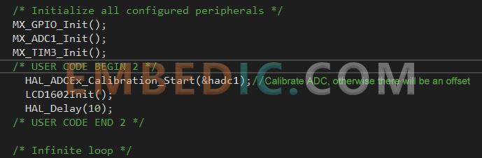
Initialize ADC, LCD
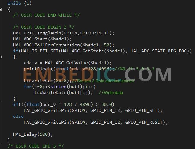
Here the ADC reading is first collected, followed by a call to printFloat to convert the floating point number to a string, followed by printing the string to the second line for display. The ADC reading is then used to determine if further heating is required based on the current ADC reading. Here the temperature is set to 30 degrees.
The program is finished, click compile and generate the hex file.
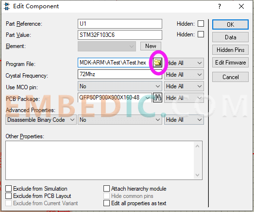
Double click on the STM32 part in Proteus, open properties, add the hex file and click OK
For MDK, the hex path is in the project MDK-ARM\ATest\ATest.hex
Click Run in the lower left corner to start the simulation
You can see that the program is starting to run normally.
However, you will find that the temperature sometimes exceeds the limit, and it is slow, and the jitter will be bigger. Here we recommend using PWM for control, and the effect is the best.
Manufacturer: Texas Instruments
IC DSP MILTICORE 561FCBGA
Product Categories: DSP
Lifecycle:
RoHS:
Manufacturer: Texas Instruments
IC DSP FIX/FLOAT POINT 361NFBGA
Product Categories: DSP
Lifecycle:
RoHS:
Manufacturer: Microchip
IC MCU 8BIT 64KB FLASH 28SDIP
Product Categories: 8bit MCU
Lifecycle:
RoHS:
Manufacturer: Analog Devices
IC DSP 16/32B 400MHZ 168CSBGA
Product Categories: DSP
Lifecycle:
RoHS:
Looking forward to your comment
Comment
1
2
3
4
5
6
 Popular Searches
8 Bit MCU, Flash, PIC16 Family PIC16F7XX Series Microcontrollers, 20 MHz, 7 KB, 192 Byte, 44 Pi...
EEPROM 2K 256 X 8 2.5V SERIAL EE IND
System-On-Modules - SOM RCM2200
32-bit Arm Cortex-A53 vision processor with ISP, powerful 3D GPU, dual APEX-2 vision accelerat...
IC MCU 8BIT 60KB FLASH 44QFP
DSP 20MHZ 44QFP
Product updates, events, and resources in your inbox


Smart System

Traffic Management

Security

Consumer Electronics

Wireless Technology

Robot

Internet of Things

Industrial Control


