Hello! Welcome to Embedic!
CubeSat began in 1999 as a scientific study by California Institute of Technology and Stanford University. With the development of mechanical and electronic industries toward miniaturization and integration as well as the diversification of space missions, CubeSat has gradually become a research hotspot in the field of space at home and abroad due to its low development cost, short development cycle, high functional density and flexible deployment.
CubeSat was born at the beginning of the new century to help graduate students at Caltech and Stanford University design, build, test and operate spacecraft with similar capabilities to the Soviet satellite Sputnik. Since then, NASA, the National Reconnaissance Office (NRO), and even the Boeing Group have launched their own CubeSat programs. There are currently more than 130 CubeSats operating in space orbit. In addition, NASA's Educational Launch of Nano satellite (ELaNa) program, previously offered to educational institutions and research missions, is now open to U.S. non-profit organizations.
The "Cube" in "CubeSats" refers to the cube shape of the satellite. The most common CubeSat (also called a 1U Sputnik) is a cube with 10 cm (about 4 feet) sides, so small that a single CubeSat could easily be mistaken for a paperweight on a table. These small modular satellites can easily be tucked into space previously wasted by launch vehicles. And multiple satellites can be used in combination to accomplish more complex missions. The satellites' pocket-sized bodies have sensors, communications receivers and signal transmitters so that ground-based operators can study the planet we live on and the space around it from space.
The STM32 series microcontrollers are 32-bit microcontrollers based on the ARMCortex⁃M core introduced by ST (STMicroelectronics), which support a wide range of 32-bit applications. The STM32F1 series chips were used to design a high precision solar tracking system based on fiber optic arrays; the STM32F4 series chips were used to complete the design of an X-type quadrotor UAV.
The STM32F4 series chips are high-performance microcontrollers based on the ultra-low-power ARM Cortex⁃M4 core. The STM32F407 series operates at up to 168 MHz and has 140 fast I/O ports and up to 15 standard communication interfaces (2 CAN interfaces, 4 USART, 2 UART, 3 I2C interfaces, 3 SPI, 1 SDIO interface). (1 SDIO interface), and can operate at low voltage (1.8~3.6 V). Based on these resources and features, the STM32F407 meets the requirements of a posture-controlled computer for low power consumption, high performance and rich interfaces. Therefore, the STM32F407 is selected as the main chip and the peripheral circuit to implement the design of the attitude control computer.
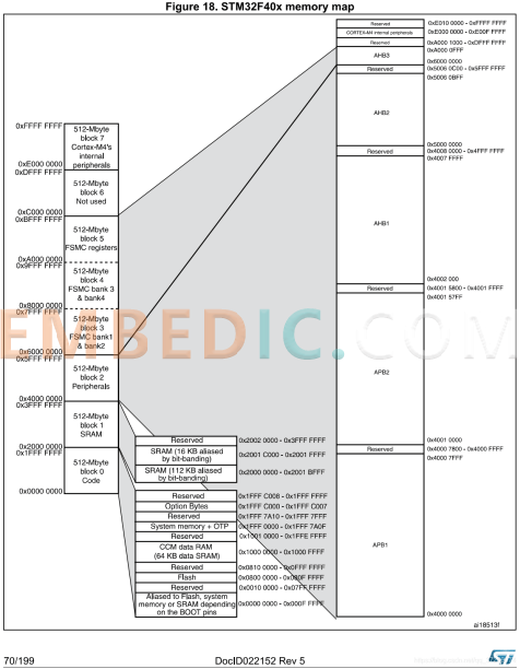
Among them, this figure contains the address information of all peripheral registers and the general running memory address. As for the 512MB size block shown on the way, it does not exist in the f407, and may exist in more advanced devices.
1. The Clock circuit uses CC5V⁃TIA⁃32.768 chip to provide the system with 32.768 kHz frequency as external clock, and two AHB buses can be configured by phase-locked spread spectrum and prescaler, high speed APB (APB2, up to 84 MHz) and low speed APB (APB1, up to 42 MHz).
2. Power Supply Circuit
In order to simplify the power supply circuit, we select the sensor and actuator components with the same power supply voltage range as much as possible, so the whole posture control system only needs two power supply standards: 5 V and 3.3 V.
The external bus power supply voltage is 7.4 V, so it needs to be realized by the voltage converter chip, this paper uses two chips, ADP3303 and LMZ12001, to realize 5 V and 3.3 V respectively. In this paper, we use ADP3303 and LMZ12001 chips to realize 5V and 3.3V power supply respectively. In order to stabilize the input and output without interference from other signals, capacitors are connected in series between the input and output pins and ground.
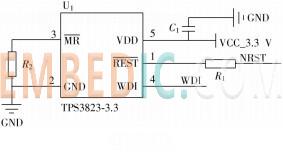
3. Reset Circuit
The TPS382X series monitors provide circuit initialization and timing monitoring for DSP and processor-based systems. This series of devices is set by the internal voltage divider a fixed detection threshold voltage, when the supply voltage is higher than the threshold voltage, generate a reset signal, when the supply voltage is lower than the threshold voltage, remain 

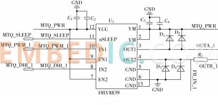
1. Magnetic torque device drive circuit
The magnetic torque is derived from the ampere force generated by the energized coil in the magnetic field, and the magnitude of the magnetic torque can be adjusted by controlling the current in the coil. The CubeSat uses the output current of the driver chip to drive the magnetic torquer. The driver chip is controlled by the PWM wave output from the I/O port of the main chip STM32F407, and the output current can be controlled by controlling the duty cycle of the PWM wave.
The driving current required for the magnetic torque device to work is below 1A, and the output voltage range of the I/O port of the main chip is 0~3.3V. Therefore, this paper selects the DRV8839 chip as the driver chip of the magnetic torque device. This chip can provide a current output up to 1.8 A, has a strong driving capability, and meets the driving requirements of the magnetic torque device. The working voltage range is 1.8~7V, which can be controlled by the The I/O port of the chip is directly controlled. The drive circuit design of the magnetic torque device is shown below.
2. Momentum wheel drive circuit
The momentum wheel selected in this paper is the 2610012B momentum wheel of Folhabe Company. The momentum wheel works under 12V voltage, the maximum speed is 6400V/min, the maximum torque is 3.1mN m, the rated torque is 2.85mN m, and the speed The constant is 543min-1/V, and the speed is controlled by the output voltage of the driver chip. The driver chip receives the control command from the attitude control computer through SPI and converts it into a voltage output to drive the momentum wheel. AD5664 is a low-power, 16-bit DACs with an operating voltage of 2.7~5.5V, compatible with standard SPI interface, and meets the above requirements.
3. Sun sensor, magnetometer interface circuit
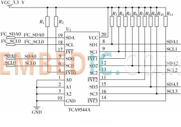
Both the sun sensor and the magnetometer communicate with the attitude control computer through I2C. This paper considers installing sun sensors on three faces of the cube satellite, one on each face, and each sun sensor generates a four-quadrant current, which is collected by two current acquisition chips INA3221Q1 and converted into digital signals, and communicated with the attitude through the I2C interface. The data is exchanged with the control computer; the signal generated by the magnetometer is converted through the amplification circuit and the A/D conversion chip ADS1115, and then exchanged with the attitude control computer through I2C.
The main chip STM32F407 integrates 3-way I2C, which does not meet the system requirements, and the I2C integrated on the chip is not stable enough, so this paper designs to use the expansion chip to expand the on-chip I2C. TCA9544A is a four-channel bidirectional conversion I2C multiplexer with a maximum frequency of 400kHz. This paper uses TCA9544A to expand one I2C channel into four channels for use by three sun sensors and magnetometers. The extended circuit is shown below.
4. Gyroscope interface circuit
The gyroscope used in this paper is ADIS16465 from ANALOG DEVICES, which is a precision microelectromechanical system (MEMS) inertial measurement unit (IMU) with a measurement range of ±250 (°)/s and a bias stability of 12° during motion. (°)/hr(1σ), the angle random walk is 0.56hr(1σ), and the signal processing module and SPI communication interface are integrated inside, so there is no need for an external conversion chip for level conversion, and it can be directly connected to the main chip of the attitude control computer The SPI communicates.
5. Star sensor interface circuit
The star sensor selected in this paper is the nano-type star sensor NST-4 of TY⁃SPACE, which is small in size, light in weight (<200g), low in power consumption (<0.6W), and high in accuracy. High (5″, 3σ), with high dynamic performance (2(°)/s, high anti-stray light performance, the communication interface is RS422. The main chip STM32F407 does not integrate RS422 communication interface in the chip, so it is necessary to use a conversion chip to convert 1 channel The serial port is converted into RS422 level for star sensor communication.
MAX3488 is a low-power transceiver for RS485 and RS422 communication, the working voltage is 3.3V. The chip features a slew⁃rate limited driver that minimizes electromagnetic interference and reduces reflections caused by incorrect cable ends, allowing error-free data transfer rates up to 250 Kb/s, meeting the requirements of this paper. Therefore, this article chooses MAX3488 to complete the level conversion of RS422.
6. GPS interface circuit
The GPS module is designed based on STM32F205 and communicates with the attitude control computer through UART. Both STM32F205 and the main chip STM32F407 have UART communication interfaces. This article uses USART1 (PA9, PA10) of STM32F205 and UART4 (PC10, PC11) of STM32F407 to communicate.

Manufacturer: Texas Instruments
IC DSP FIX/FLOAT POINT 176HLQFP
Product Categories: DSP
Lifecycle:
RoHS:
Manufacturer: Texas Instruments
IC DSP FIX/FLOAT POINT 841FCBGA
Product Categories: DSP
Lifecycle:
RoHS:
Manufacturer: Texas Instruments
IC DSP FIX/FLOAT POINT 361NFBGA
Product Categories: DSP
Lifecycle:
RoHS:
Manufacturer: Analog Devices
IC DSP 400MHZ 1.4V 120LQFP
Product Categories: DSP
Lifecycle:
RoHS:
Looking forward to your comment
Comment
1
2
3
4
5
6
 Popular Searches
8 Bit MCU, Flash, PIC16 Family PIC16F7XX Series Microcontrollers, 20 MHz, 7 KB, 192 Byte, 44 Pi...
EEPROM 2K 256 X 8 2.5V SERIAL EE IND
System-On-Modules - SOM RCM2200
32-bit Arm Cortex-A53 vision processor with ISP, powerful 3D GPU, dual APEX-2 vision accelerat...
IC MCU 8BIT 60KB FLASH 44QFP
DSP 20MHZ 44QFP
Product updates, events, and resources in your inbox


Smart System

Traffic Management

Security

Consumer Electronics

Wireless Technology

Robot

Internet of Things

Industrial Control


