Hello! Welcome to Embedic!
Infrared remote control has been widely used in various types of home appliances, and its appearance provides a lot of convenience for using home appliances. Infrared remote control system generally consists of two parts: infrared transmitting device and infrared receiving equipment. Infrared emission device can be composed of keyboard circuit, infrared coding chip, power supply and infrared emission circuit.
Infrared remote control has been widely used in various types of home appliances, and its appearance provides a lot of convenience for using home appliances. Infrared remote control system generally consists of two parts: infrared transmitting device and infrared receiving equipment. Infrared emission device can be composed of keyboard circuit, infrared coding chip, power supply and infrared emission circuit. The infrared receiving device can be composed of infrared receiving circuit, infrared decoding chip, power supply and application circuit. Usually in order to make the signal better to be transmitted, the baseband binary signal is modulated into a pulse train signal by the sending end, which is transmitted through an infrared transmitting tube. This design uses Atmega8 as the infrared emission encoding and receiving and decoding chip.
The infrared remote control circuit of a complete lighting lamp should have the following functions:
Press any switch to enable the corresponding lamp to turn on and off, press the main switch to turn on and off all the lights, and press the corresponding timing off button to turn off the lights within the set time.
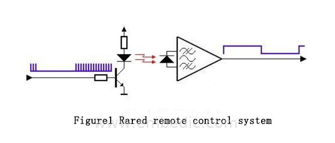
The universal infrared remote control system consists of three parts: modulation, emission and reception. This system uses Atmega8 microcontroller as infrared emission encoding and receiving decoding chip, and HS5104 as emission encoding chip. Three of the five keyboard input modules are used for The three lights are turned on and off respectively, a keyboard input module is used to operate all lights on and off, and the last remaining keyboard input module is used to realize the function of turning off the lights within a set time. The infrared remote control system is shown in Figure 1:
(1) Launch system
The transmission system is generally powered by a battery, which requires that the power consumption of the chip be very low. Most of the chips are designed to be in a sleep state and only work when a button is pressed, which can reduce power consumption. Infrared rays are emitted through infrared light-emitting diodes (LEDs). The internal materials of infrared light-emitting diodes are different from ordinary light-emitting diodes. When a certain voltage is applied to its two ends, it emits infrared rays instead of visible light.
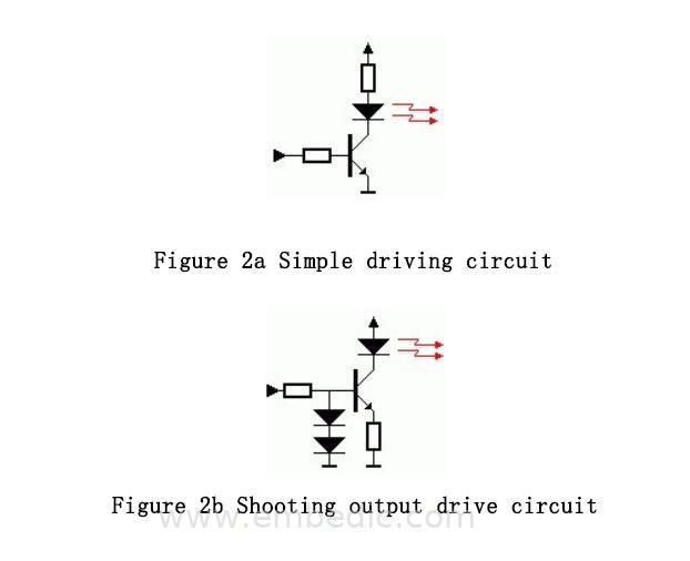
Figure 2a and Figure 2b are the LED drive circuits. Figure 2a is the simplest circuit. When selecting components, pay attention to the fast switching speed of the transistor, and also consider the forward current and reverse leakage current of the LED, which generally flow through the LED. The maximum forward current of is 100mA, the greater the current, the greater the intensity of the transmitted waveform.
The circuit in Figure 2a has a little defect. When the battery voltage drops, the current flowing through the LED will decrease, the intensity of the transmitted waveform will decrease, and the remote control distance will decrease. The emitter output circuit shown in Figure 2b can solve this problem. Two diodes clamp the base voltage of the triode at about 1.2V, so the emitter voltage of the triode is fixed at about 0.6V, and the emitter current IE is basically not According to IE≈IC, the current flowing through the LED is basically unchanged, which ensures that a certain remote control distance can be ensured when the battery voltage drops.
(2) Receiving system
The typical circuit of the infrared signal receiving system is shown in Figure 3a:
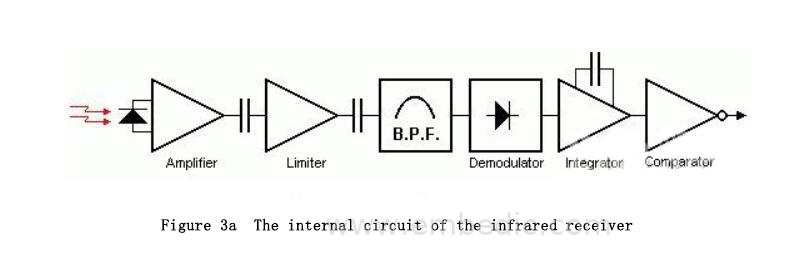
The circuit includes infrared monitoring diode, amplifier, limiter, band pass filter, integrating circuit, comparator, etc. The infrared monitoring diode monitors the infrared signal, and then sends the signal to the amplifier and limiter. The limiter controls the pulse amplitude at a certain level, regardless of the distance between the infrared transmitter and the receiver. The AC signal enters the band-pass filter. The band-pass filter can pass the load wave of 30khz to 60khz, enter the comparator through the demodulation circuit and the integration circuit, and the comparator outputs high and low levels to restore the signal waveform at the transmitter. Note that the high and low levels of the output are inverted from the transmitter. The purpose of this is to improve the sensitivity of the receiver.
The above circuit is integrated in one component to become an integrated infrared receiver, as shown in Figure 3b:
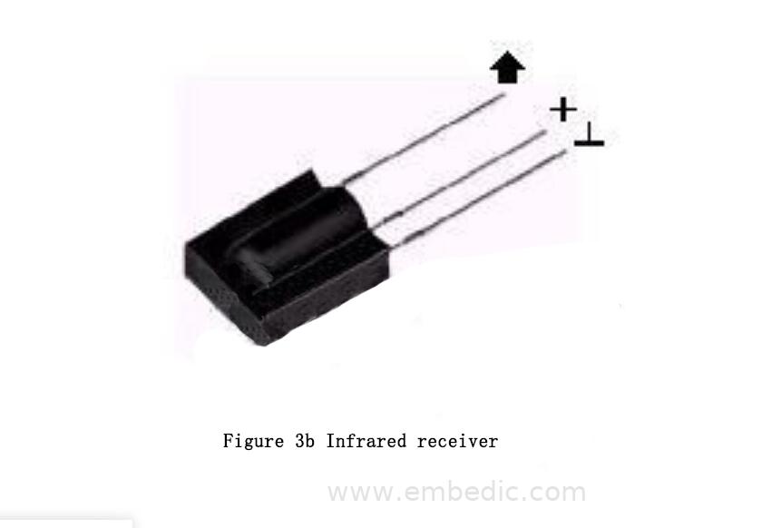
There are many types of infrared receivers with different pin definitions. Generally, there are three pins, including power supply pin, ground and signal output pin. The receiving head of the corresponding demodulation frequency should be selected according to the different modulation carrier of the transmitting end.
The gain of the internal amplifier of the infrared receiving head is very large and it is easy to cause interference. Therefore, a filter capacitor must be added to the power supply pin of the receiving head, generally above 22uf. Some manufacturers recommend connecting a 330 ohm resistor between the power supply pin and the power supply to further reduce power interference.
(3) Modulation
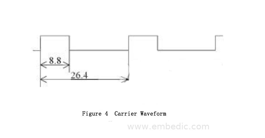
When infrared remote control transmits data, a modulation method is adopted, that is, the data is ANDed with a certain frequency carrier, which can improve the transmission efficiency and reduce the power consumption.
The modulated carrier frequency is generally between 30khz and 60khz, most of which use a 38kHz square wave with a duty cycle of 1/3, as shown in Figure 3.4, which is determined by the 455kHz crystal used at the transmitter. At the transmitting end, the crystal oscillator must be divided by integer frequency, and the frequency division coefficient is generally 12, so 455kHz÷12≈37.9kHz≈38kHz.
3.2 Circuit schematic diagram of each module
(1) Introduction to Atmega8MCU
The control core of the system, Atmega8 microcontroller, is an 8-bit high-performance microcontroller based on AVR RICS low-power CMOS launched by Atmel. Due to its advanced instruction set and single clock cycle instruction execution time, ATmega8's data throughput rate is as high as 1MIPS/MHz, which can ease the contradiction between system power consumption and processing speed. Figure 6 is its pin layout diagram.
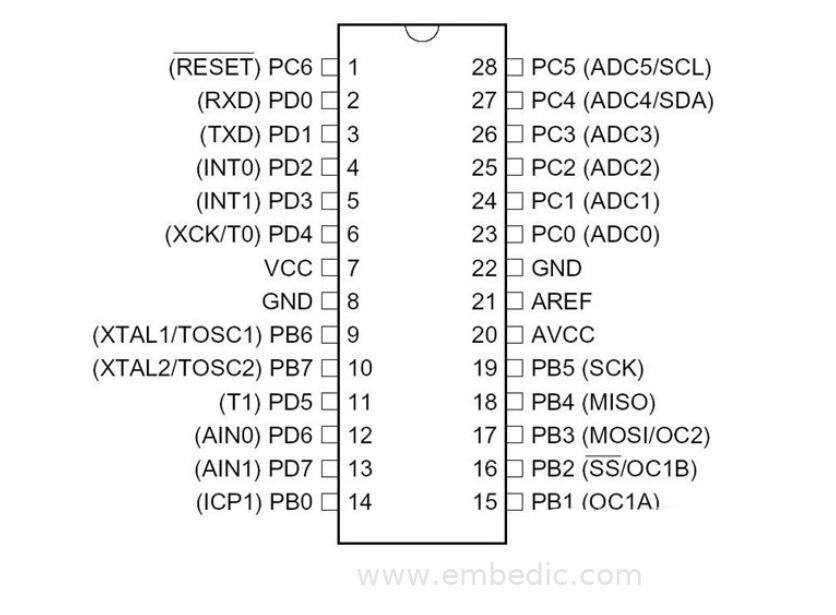
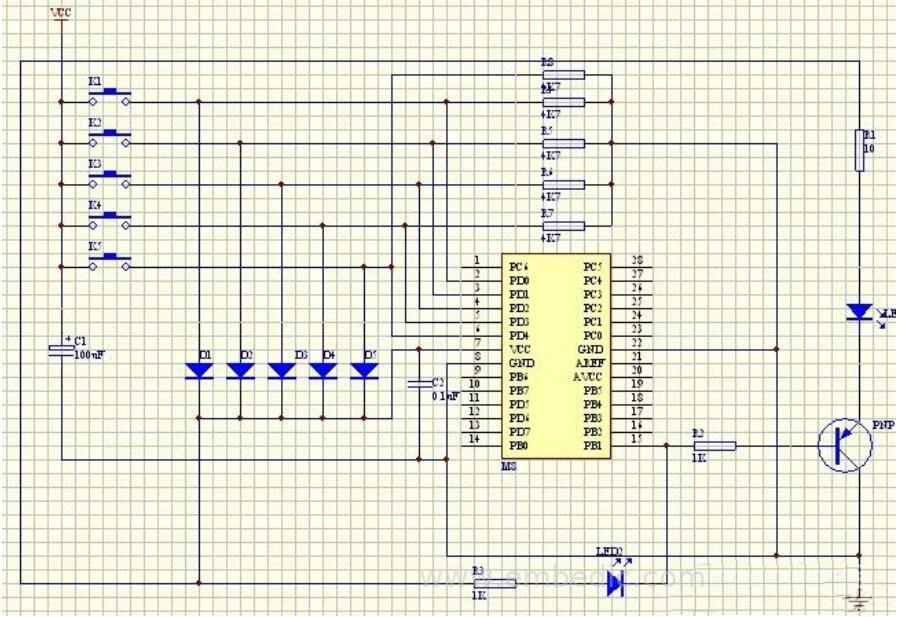
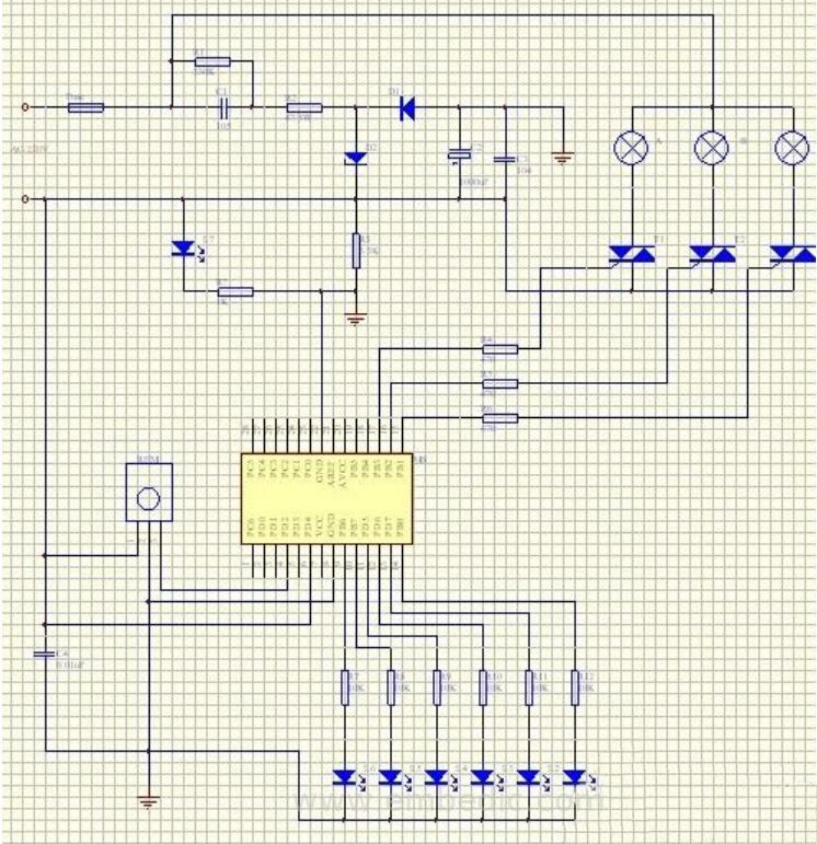
In the transmitting circuit in this design, the PC6 and PD0~PD3 ports of the Atmega8 microcontroller are used for keyboard input; the PB1 port is connected to the infrared light-emitting diode and the transmitting indicator. In the receiving circuit, PB1~PB3 of the Atmega8 microcontroller are used to connect three-way electric lights, PD5~PD7, PB0, PB6, PB7 are connected to six-way indicator lights, and PD2 is connected to the infrared receiver.
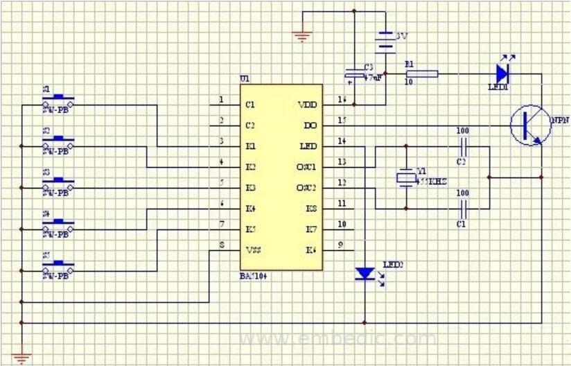
(2) HS5104 infrared remote control code transmitting circuit
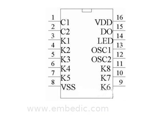
In this design, an encoder BA5104 is additionally used to form an infrared transmitting circuit. K1~K8 and ground form a key switch circuit, here only K1~K5 are used. The instruction is amplified by the transistor Q and drives the L1 infrared transmitter to emit the encoded infrared remote control signal. The HS5104 pin layout is shown in Figure 7:
(3) Other circuits
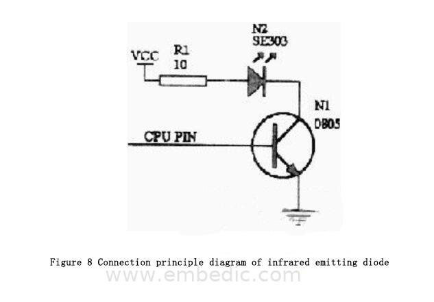
The connection of the infrared emitting diode is shown in Figure 8:
3.3 System circuit schematic diagram
The hardware schematic diagram of the transmitting circuit is shown in Figure 9a and 9b.
The hardware schematic diagram of the receiving circuit is shown in Figure 9c:

IC MCU 16BIT 32KB FLASH 44TQFP
IC MCU 32BIT 32KB FLASH 64TQFP
IC MCU 8/16BIT 64KB FLASH 44TQFP

IC MCU 8BIT 16KB FLASH 24SOIC
1
2
3
4
5
6


Product updates, events, and resources in your inbox


Smart System

Traffic Management

Security

Consumer Electronics

Wireless Technology

Robot

Internet of Things

Industrial Control