Hello! Welcome to Embedic!
The minimum system of the microcontroller, or the minimum application system, is a system that can work with the minimum number of components that make up the microcontroller. For the MSP430 series microcontroller, the minimum system should generally include: microcontroller, crystal circuit, reset circuit.
This paper introduces the characteristics of the MSP430F149 microcontroller, designs the circuit schematic diagrams of the power supply module, the crystal circuit module, the reset circuit module, the serial communication module, and the data storage module in the MSP430 minimum system, and describes the functions of each part.
Microcontroller chip with the necessary external devices, generally including power supply into and power switch, reset circuit, crystal, input and output circuits can constitute the minimum system.
MSP430F149 chip is an ultra-low-power microprocessor with 60KB+256-byte FLASH, 2KBRAM, including the basic clock module, watchdog timer, 16-bit timer with 3 capture/comparison registers and PWM outputs, 16-bit timer with 7 capture/comparison registers and PWM outputs, 2 8-bit parallel ports with interrupt function, 4 8-bit parallel port, analog comparator, 12-bit A/D converter, 2 serial communication interface and other modules.MSP430F149 chip has the following characteristics:
1) low power consumption: voltage 2.2V, clock frequency of 1MHz, the active mode is 200μA; off mode is only 0.1A, and has five energy-saving mode of operation.
2) High-efficiency 16-bit RISC-CPU, 27 instructions, 8MHz clock frequency, the instruction cycle time of 125ns, the vast majority of instructions in a clock cycle is completed; 32kHz clock frequency, 16-bit MSP430 microcontroller execution speed is higher than the typical 8-bit microcontroller 20MHz clock frequency execution speed.
3) low-voltage power supply, wide operating voltage range: 1.8 ~ 3.6V;
4) Flexible clock system: two external clocks and an internal clock;
5)Low clock frequency enables high-speed communication;
6)Serial on-line programming capability;
7)powerful interrupt function;
8)Short wake-up time, wake-up from low-power mode takes only 6μs;
9) ESD protection, strong anti-interference;
10) operating ambient temperature range of -40 ~ +85 ℃, suitable for industrial environments.
MSP430 series microcontroller control of all peripheral modules are realized through special registers, so its program writing is relatively simple. Programming development through a dedicated programmer, you can choose assembly or C language programming, IAR company for the MSP430 series of microcontrollers developed a special C430 language, can be compiled and debugged directly through WORKBENCH and C-SPY, the use of flexible and simple.
The minimum system is composed of the basic circuits necessary to ensure the reliable operation of the processor, mainly including power supply circuits, clock circuits, reset circuits, communication interface circuits, data storage circuits, and its hardware block diagram.
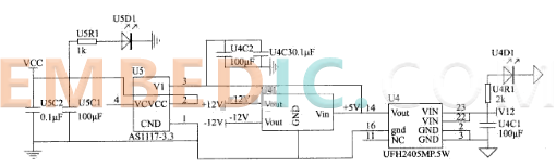
This system requires the use of +5V and +3.3V DC regulated power supply, of which the MSP430Fl49 and some peripheral devices require +3.3V power supply, and the other part requires +5V power supply. In this system, +5V DC voltage as the input voltage, +3.3V by +5V direct linear buck. The principle of the power supply circuit is shown in Figure 1.
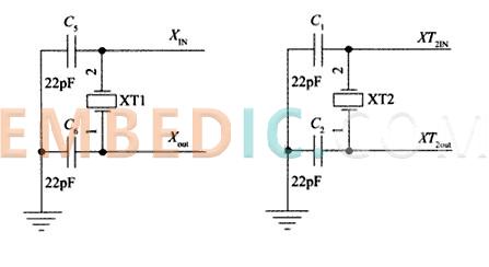
MSP430 series microcontroller clock module includes three clock sources such as numerically controlled oscillator (DCO), high-speed crystal oscillator and low-speed crystal oscillator. This is to solve the contradiction between the system's rapid data processing requirements and low-power requirements, through the design of multiple clock sources or for the clock to design a variety of different operating modes, in order to solve the clock requirements of certain peripheral components of the real-time applications, such as low-frequency communication, LCD display, timers, counters and so on. Digitally controlled oscillator DCO has been integrated into the MSP430 internal, in the system only need to design a high-speed crystal oscillator and low-speed crystal oscillator two parts of the circuit.
Low-speed crystal oscillator (LFXTl) to meet the low-power consumption and the use of 32.768kHz crystal requirements. LFXTl oscillator works in low-frequency mode by default, i.e., 32.768kHz, but also through the external 450kHz ~ 8MHz high-speed crystal oscillator or ceramic resonator working in high-frequency mode, in this circuit we use low-frequency mode, the crystal is connected to the two external 22pF capacitors connected to the MCU via XIN and XOUT.
The high-speed crystal is also known as the second oscillator XT2, which provides a clock for the MSP430F149 to work in high-frequency mode, XT2 up to 8 MHz. 4MHz crystal is used for XT2 in the system, and the XT2 is connected to the MCU with two 22pF capacitors connected to the MCU via XT2IN and XT2OUT, the principle of the reset circuit is shown in Figure 2.
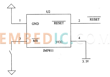
Manual reset is a common function of the minimum system, the system uses a special reset chip IMP811 to realize manual reset, the principle is shown in Figure 3.
The communication interface is responsible for the exchange of data with the peripheral serial host and support tasks such as printing.
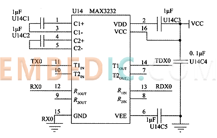
Serial communication requires only a small number of ports to realize the interoperability of microcontrollers and PCs, with unparalleled advantages. There are two ways of serial communication: asynchronous mode and synchronous mode. the MSP430 series have USART modules to realize serial communication. In this design, the USART0 module of the MSP430F149 communicates with the peripheral serial host through the RS232 serial port.
The EIA-RS232 standard is a serial data transmission bus standard developed by the Electronic Industries Association (EIA). Early it was applied to computers and terminals through the telephone line and Modem for long-distance data transmission, with the development of micro-computers and micro-controllers, not only long-distance, near distance also use the communication method. In the short distance communication system, no longer use the telephone line and MODEM, and directly end to end connection. RS232 standard uses negative logic, standard logic "1" corresponds to -5V ~ -15V level, standard logic "O" corresponds to +5V ~ +15V level, standard logic "O" corresponds to +5V ~ +15V level, standard logic "O" corresponds to +5V ~ +15V level. The standard logic "1" corresponds to -5V to -15V level and the standard logic "O" corresponds to +5V to +15V level. Obviously, communication between the two must go through the signal level conversion.
This system uses a dedicated level conversion chip MAX3232 to achieve. MAX3232 chip is MAXIM level conversion chip, including two-way receiver and driver, reliable performance. The principle is shown in Figure 4.
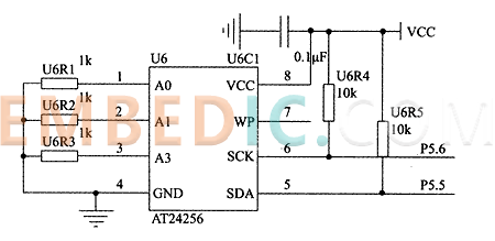
Data storage selection of large-capacity E2PROMCAT24WC256. it is a 256K-bit serial CMOSE2PROM, containing 32768 bytes, 8 bits per byte, CATALYST's advanced CMOS technology reduces the device's power consumption, CAT24WC256 has a 64-byte page write buffer that the device operates through the I2C bus interface for operation. The principle is shown in Figure 5.
The minimum system can be directly used as a core component in engineering and scientific research, with good generality and scalability. On the basis of the minimum system, it is easy to carry out secondary development and function expansion, which can shorten the development cycle and reduce the development cost. This paper realizes the basic functions of the minimum system and introduces the hardware circuit of each module. The minimum system can be appropriately modified for electronic design, computer teaching and research, industrial control and other fields.

Manufacturer: Texas Instruments
IC DSP FIX/FLOAT POINT 841FCBGA
Product Categories: DSP
Lifecycle:
RoHS:
Manufacturer: Microchip
IC MCU 16BIT 64KB FLASH 28SSOP
Product Categories: 16bit MCU
Lifecycle:
RoHS:
Manufacturer: Texas Instruments
IC DGTL MEDIA PROCESSOR 529FCBGA
Product Categories: DSP
Lifecycle:
RoHS:
Manufacturer: Microchip
IC MCU 8BIT 16KB FLASH 28SSOP
Product Categories: 8bit MCU
Lifecycle:
RoHS:
Looking forward to your comment
Comment
1
2
3
4
5
6
 Popular Searches
8 Bit MCU, Flash, PIC16 Family PIC16F7XX Series Microcontrollers, 20 MHz, 7 KB, 192 Byte, 44 Pi...
EEPROM 2K 256 X 8 2.5V SERIAL EE IND
System-On-Modules - SOM RCM2200
32-bit Arm Cortex-A53 vision processor with ISP, powerful 3D GPU, dual APEX-2 vision accelerat...
IC MCU 8BIT 60KB FLASH 44QFP
DSP 20MHZ 44QFP
Product updates, events, and resources in your inbox


Smart System

Traffic Management

Security

Consumer Electronics

Wireless Technology

Robot

Internet of Things

Industrial Control


