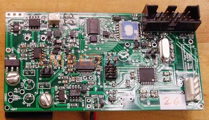
A microcontroller reset circuit is a circuit designed to ensure that a microcontroller (microcontroller) will function properly at startup or under abnormal conditions. The main function of a reset circuit is to restore the internal state and registers of the microcontroller to a known initial state so that program execution can begin.

A microcontroller reset circuit usually consists of the following major components:
Reset Pin: There is usually a dedicated reset pin on the microcontroller for receiving external reset signals. When this pin receives a reset signal, the microcontroller is forced to restart and zero out or set its internal state to a predefined initial state.
RESET CIRCUIT: The reset circuit usually consists of a resistor, capacitor and/or voltage regulator used to generate an appropriate reset pulse signal. This signal is passed to the reset pin of the microcontroller to trigger a reset operation.
Reset Controller: Some microcontrollers have an internal reset controller that monitors parameters such as supply voltage, clock, etc. to determine when to trigger a reset operation. This prevents the microcontroller from operating incorrectly if the supply voltage is unstable or the clock is incorrect.
Reset Vector: During a reset, the microcontroller jumps to a specific reset vector address from where it starts executing the initialization routine. This vector address is usually fixed and determined by the manufacturer of the microcontroller.
A microcontroller reset circuit is a very important part of a microcontroller system, its main function is to change the power supply voltage to the microcontroller from high to low so that the microcontroller can start working again. A microcontroller reset circuit usually consists of a resistor and a switch. When the switch is pressed, the resistor is energized to change the supply voltage to the microcontroller from high to low, thus enabling the reset operation.
A microcontroller reset circuit usually consists of two parts: an external reset circuit and an internal reset circuit. The external reset circuit is triggered by an external switch. When the switch is pressed, the reset circuit is activated, thus changing the level state inside the microcontroller to the initial state. The internal reset circuit, on the other hand, is realized by a circuit inside the microcontroller, which can be software controlled or hardware triggered to realize the reset operation.
In the microcontroller reset circuit, the resistor is a very important component. In external reset circuits, resistors are usually connected between the reset pin and ground to limit the size of the reset current; while in internal reset circuits, resistors are used to control the strength and timing of the reset signal. In addition, pull-up or pull-down resistors are also frequently used components that can change the level state of a pin to control the operating state of the microcontroller.
The design of the microcontroller reset circuit needs to take into account a number of factors, including the type of microcontroller, operating voltage, reset mode and so on. In the actual design process, it is necessary to select the appropriate reset circuit scheme according to the specific application scenario, and carry out detailed design and debugging work. Only after adequate testing and verification can the reliability and stability of the microcontroller system be ensured.
External Reset Circuit: The external reset circuit uses an external switch as the reset signal. When the switch is pressed, it is connected to a resistor that changes the supply voltage of the microcontroller from high to low. This type of reset circuit is usually used when a manual reset is required.
Internal Reset Circuit: The internal reset circuit uses a flip-flop inside the microcontroller to realize the reset operation. When the flip-flop is activated, it changes the power supply voltage of the microcontroller from high to low, thus realizing the reset operation. This type of reset circuit is usually used in cases where a manual reset is not required.
Watchdog Reset Circuit: The watchdog reset circuit uses a watchdog timer to realize the reset operation. When a problem occurs in the operation of the microcontroller, the watchdog timer will automatically reset the microcontroller to realize the reset operation. This type of reset circuit is usually used in situations where real-time monitoring of the microcontroller's operating status is required.
Manufacturer: Texas Instruments
IC DSP FIX/FLOAT POINT 841FCBGA
Product Categories: DSP
Lifecycle:
RoHS:
Manufacturer: Texas Instruments
IC DSP FIX/FLOAT POINT 625FCBGA
Product Categories: DSP
Lifecycle:
RoHS:
Manufacturer: Texas Instruments
IC DGTL MEDIA PROCESSOR 529FCBGA
Product Categories: DSP
Lifecycle:
RoHS:
Manufacturer: Texas Instruments
IC DGTL MEDIA PROCESSOR 529FCBGA
Product Categories: DSP
Lifecycle:
RoHS:
Looking forward to your comment
Comment