Hello! Welcome to Embedic!
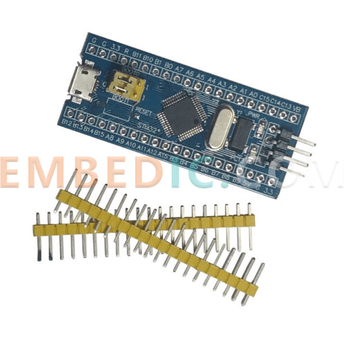
STM32F103C8T6 MCU is increasingly widely used in various fields of production life, external rich sensors, function modules, communication modules, display storage, etc. can form a variety of product project applications. For products with high power requirements, the STM32L series MCUs are generally chosen, but from the perspective of power consumption reviews, the logic is basically similar.
In many applications are very demanding power consumption requirements for electronic devices, such as certain sensor information acquisition equipment, relying only on a small battery to provide power, requiring work for up to several years, and during the period does not require any maintenance.
Due to the miniaturization requirements of smart wearable devices, the battery size can not be too large resulting in a relatively small capacity, so it is also necessary to control power consumption to improve the endurance of the device.
In fact, as long as it involves portable products, it is inevitable to use the battery as a power source, otherwise, if it is still necessary to connect a plug to use the mains to power, it can not be called portable, such as cell phones, sports bracelets, Bluetooth headphones, smart watches and other similar. So it is especially important to control power consumption and improve the product life time.
At present, for STM32F103C8T6 and other series of microcontrollers, the more common low-power modes are stop mode and standby mode.
When using standby mode, in practical applications, there is usually an on/off button (PA0), if the user presses the button, the power will be turned on or off, on corresponds to wake-up, and off corresponds to standby (similar to the on/off button of a cell phone).
In this process, the battery will always give the microcontroller's 3.3V power supply, that is, the microcontroller is always powered, but all of its peripherals and the clock are off, the reason for the microcontroller power supply, just to detect the rising edge of PA0 when the user presses the button, if not to the microcontroller power supply, then how to detect it? Detection can not.
When using stop mode, we first look at a problem: theoretically, the power consumption of standby mode is much lower than the stop mode, why choose stop mode?
This is usually the case, a portable system, in addition to considering the key switch, but also need to consider charging the battery often need to display some charging information (now the phone charging is this), if it is in the power-on state charging is no problem at all. However, if it is in the off state charging it? It is definitely necessary for the microcontroller to be able to wake itself up (without the user pressing PA0), and then it is possible to display information about charging (for example, the phone can automatically display the animation of charging when it is powered on in the off state).
Is it possible to achieve the wake-up function without pressing PA0? Of course it is possible, it only requires some changes in hardware.
For example, the voltage of the charging port will be stepped down and connected to PA0, so that as long as the charging port is charging, PA0 will definitely show a pulse from low to high, so that it can wake up. However, in this case, it is not easy to distinguish at the software level whether the rising edge of PA0 is caused by charging or by the user pressing a key.
So, this time it is necessary to consider choosing the stop mode. The on/off button is connected to one pin and the charging port is connected to another pin, both pins are configured as external interrupts and both pins can also wake up the microcontroller, separating the different signal levels, this way, it is easy to judge in software.
In fact, there is another way to improve the hardware is to implement a pulse circuit, you can use a simple RC delay circuit, that is to say, the level of the charging port and then after an RC circuit, out will not always be a high level, but only a pulse, and then the pulse signal to the PA0 pin, this time inserted into the charging port and press PA0 will appear in PA0 on a pulse on PA0.
Software, you can use the mechanism of long press on, and then long press off to discriminate, if PA0 just appear a rising edge and detect the charging chip is charging, this is the charging port is inserted, wake up the microcontroller and display the charging effect can be.
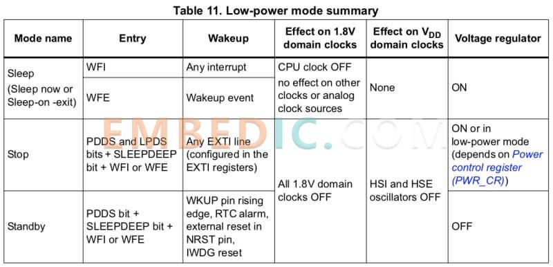
Let's first understand the several operating modes of the STM32F103C8T6 microcontroller. In descending order of power consumption, the STM32F103C8T6 has four modes of operation: Run, Sleep, Stop and Standby. In these four modes, the last three are the modes that can be selected when the STM32F103C8T6's core is not in need of running, and the run mode when the microcontroller is working.
Here we do not talk much about the run mode, because when the STM32F103C8T6 is in the run mode after power-on reset, in this case, the microcontroller automatically runs the program. Only when we do not need the core, which is called Cortex-M3, to continue to run, we can choose to let the chip into the sleep, stop and standby modes, to let the chip reduce power consumption. The reduction of power consumption will reduce the heat of the chip as well as ensure increased reliability.
When the STM32F103C8T6 is running, the core, also known as Cortex-M3, will stop the internal clock and stop program execution when it encounters a WFE (wait for interrupt) or WFI (wait for event) instruction.
Although the Cortex-M3 stops working, its peripherals continue to work until a peripheral generates an event or interrupt, when the kernel will be woken up and exit sleep mode. In sleep mode, only the kernel clock is turned off and the kernel stops running, but the on-chip peripherals, the peripherals of the Cortex-M3 core, all continue to run as usual, and no new code is executed in software.
This state retains the kernel registers and memory data before sleep. After waking up, if waking up by interrupt, it will first enter the interrupt, exit the interrupt service program, and then execute the program after WFI instruction; if waking up by event, it will directly execute the program after WFE. Basically, there is no wake-up delay.
One additional thing here: Cortex-M3 is a 32-bit core, which has some requirements different from general-purpose 32-bit CPU applications in the traditional microcontroller field. In the field of industrial control, users require faster interrupt speed. Cortex-M3 adopts Tail-Chaining interrupt technology, which is completely hardware-based for interrupt processing, reducing the number of clock cycles by up to 12, which can reduce interrupts by 70% in practical applications.
If the user sets the SLEEPDEEP bit in the Cortex Power Control Register (Cortex_PCR) of the Cortex-M3 processor, then sets the PD bit in the STM32F103C8T6 Power Control Register (STM32 PCR). Then clear the PDDS (Power Down Deep Sleep) bit in the STM32 PCR to complete the STM32F103C8T6 shutdown mode setting.
When the shutdown mode is set, the CPU will stop once it encounters a WFI or WFE instruction, and the HSI and HSE will go into the shutdown state. However, the Flash and SRAM will continue to be powered on, so all operating states of the STM32F103C8T6 are still preserved at this time.
Like sleep mode, shutdown mode can also be woken up by a peripheral interrupt, however, in shutdown mode, all device clocks are disabled except for the external interrupt control unit, and the STM32 can only be woken up from the shutdown state by generating a level edge on the GPIO pins to trigger an external interrupt.
Note that the external interrupt channel is connected to the GPIO in addition to the alarm event of the RTC clock, plus the counting clock of the RTC does not come from the device bus of the STM32F103C8T6 (but directly from the LSI or LSE), so it is also possible to use the RTC module to implement a timed wake-up of the STM32F103C8T6 from the downtime state.
If the SLEEP bit in STM32F103C8T6 power control register is set, and then the PDDS bit in STM32_PCR is set, so that the microcontroller is in standby mode.
To wake up the standby mode, there are several ways to wake up the microcontroller: alarm event of RTC, external pin reset of NRST, reset signal generated by independent watchdog (IWDG), and a rising edge generated by PA0 pin, but if you want the rising edge generated by this pin to wake up the microcontroller, you must set the wake-up pin function in advance.
Standby mode is the lowest power consumption mode of the STM32F103C8T6. When entering standby mode, all SRAM data, Cortex-M3 processor registers and STM32F103C8T6 register contents will be cleared to zero, which has the same effect as a hardware reset.
First, in order to maintain the accuracy of the review, we first use a resistive load to verify the accuracy of the device test, the resistance is 0.1% precision 100K resistor, so the resistance error of the resistor we can first ignore.
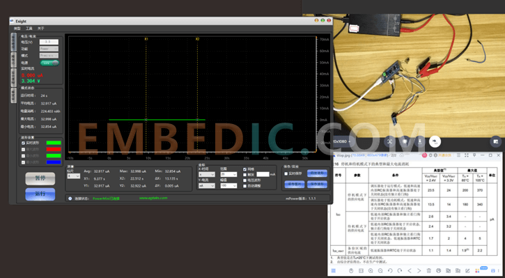
Turn on the power consumption analyzer power mPower1203 test equipment, set the 3.3V output. As you can see, the current value flowing through the resistor is displayed on the accompanying E-sight tool. Theoretically, it is 33uA, and the difference between our measured value and the theoretical value is tens of nA, so basically the current accuracy of the device can reach within one thousandth of the accuracy.
Now start to evaluate the power consumption of the STM32F103C8T6 microcontroller in several modes of hibernation.
Sleep mode
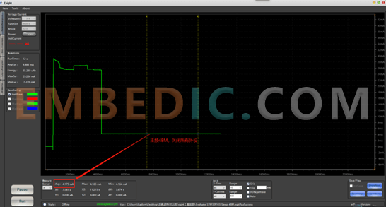
We can see from the STM32F103C8T6 microcontroller's specification that using an external clock, with the main frequency at 72MHz and 48MHz and all peripherals turned off, the typical values of power consumption are about 5.5mA and 3.9mA, and we evaluate the test around these two values.
After testing and waveform analysis.
Top graph
Bottom graph
The test data basically conforms to the typical value data in the specification. From this data, we can understand that when a product needs to optimize power consumption, in some occasions, the target power consumption can be obtained by reducing the main frequency.
Shutdown mode
From the specification of STM32F103C8T6 MCU, we can see that the power supply output is 3.3V and there are two cases in the shutdown mode. One is that the regulator is in run mode, corresponding to a typical value of power consumption of 24uA; the other is that the regulator is in low-power mode, corresponding to a typical value of power consumption of 14uA. we test around these two values for evaluation.
After testing and waveform analysis.
The test data basically conforms to the typical value data in the specification. In configuring the STM32F103C8T6 microcontroller into the shutdown mode, a special point to note is that the external pin connected to the 8M crystal needs to be configured as a normal GPIO, and also needs to be configured as an analog input.
Standby mode
From the STM32F103C8T6 microcontroller specifications, we can see that the power supply output 3.3V, there are three cases in standby mode. These three cases correspond to typical values of power consumption of about 3.4uA, 3.2uA, and 2uA, respectively, and we evaluate the tests around these three values.
After testing and waveform analysis.
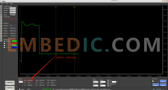
Figure 1: Standby power consumption of 2.912uA with both internal RC and standalone watchdog on.
Figure 2: Standby power consumption of 2.702uA with the internal RC on and the standalone watchdog off.
Figure 3: internal RC and independent watchdog are both off, and the low-speed oscillator and RTC are both off, with a standby power consumption of 1.62uA.
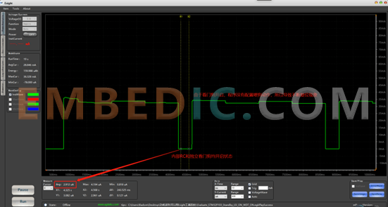
Figure 1
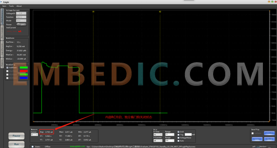
Figure 2
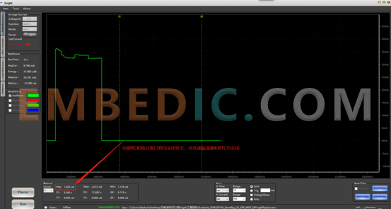
Figure 3
The test data basically conforms to the typical value data in the specification.
Finally, it should be mentioned that when we conduct the power consumption evaluation, we need to understand the meaning of typical values when comparing with the specification. In general, the values in the specification are relatively conservative, and the typical value is a 1σ value in a normal distribution, which means that 68.27% of the probability of falling around the typical value. In other words, a total of 100 test samples, 68.27 samples of the test data is to meet the typical value.

Manufacturer: Microchip
IC MCU 8BIT 14KB FLASH 44QFN
Product Categories: 8bit MCU
Lifecycle:
RoHS:
Manufacturer: Texas Instruments
IC DSP 181CPGA
Product Categories: DSP
Lifecycle:
RoHS:
Manufacturer: Texas Instruments
IC DGTL MEDIA PROCESSR 1031FCBGA
Product Categories: DSP
Lifecycle:
RoHS:
Manufacturer: Microchip
IC MCU 8BIT 28KB FLASH 40UQFN
Product Categories: 8bit MCU
Lifecycle:
RoHS:
Looking forward to your comment
Comment
1
2
3
4
5
6
 Popular Searches
8 Bit MCU, Flash, PIC16 Family PIC16F7XX Series Microcontrollers, 20 MHz, 7 KB, 192 Byte, 44 Pi...
EEPROM 2K 256 X 8 2.5V SERIAL EE IND
System-On-Modules - SOM RCM2200
32-bit Arm Cortex-A53 vision processor with ISP, powerful 3D GPU, dual APEX-2 vision accelerat...
IC MCU 8BIT 60KB FLASH 44QFP
DSP 20MHZ 44QFP
Product updates, events, and resources in your inbox


Smart System

Traffic Management

Security

Consumer Electronics

Wireless Technology

Robot

Internet of Things

Industrial Control


