Hello! Welcome to Embedic!
Welcome to this article about the ADC reference voltage of PIC16F series microcontrollers! If you're working with these microcontrollers, you're probably aware that the Analog-to-Digital Converter (ADC) is a key component for converting analog signals into digital values that can be processed by the microcontroller. However, one critical aspect of ADC operation is the reference voltage that is used to compare the input voltage to determine its digital value.
In this article, we'll dive into the details of ADC reference voltage for the PIC16F series microcontrollers, including how it works, its importance in ADC accuracy, and how to configure it for your specific application. So, whether you're just starting out with PIC16F microcontrollers or are looking to optimize your ADC performance, this article will provide valuable insights and practical tips.
PIC16F series microcontroller is a family of low-cost, high-performance 8-bit microcontrollers designed by Microchip Technology. These microcontrollers are widely used in a variety of applications such as consumer electronics, automotive, industrial automation, and medical devices.
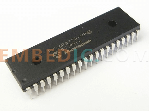
The PIC16F series microcontroller features a wide range of peripherals, including analog-to-digital converters, digital-to-analog converters, timers, UARTs, SPIs, and I2Cs. The microcontroller also has a flexible and easy-to-use architecture, which enables designers to create customized solutions for their applications.
Additionally, the PIC16F series microcontroller has a low power consumption, which makes it ideal for battery-operated devices. The microcontroller is programmed using Microchip's MPLAB IDE, which is a free, integrated development environment that includes a debugger, assembler, and simulator. Overall, the PIC16F series microcontroller is a versatile and cost-effective solution for embedded system applications.
Download PIC16F pdf datasheet here.
Here are some of the pros and cons of the PIC16F series microcontroller:
Pros:
Cons:
ADC stands for Analog to Digital Converter. It is a device or a module that converts analog signals into digital signals. An analog signal is a continuous signal that varies in amplitude and frequency over time, whereas a digital signal is a binary signal with discrete levels representing the original analog signal.
Reference voltage is the voltage against which the analog signal is compared to produce a digital output. In other words, it is the voltage level that the ADC uses as a reference point to convert the analog signal into a digital signal.
The reference voltage is important in the ADC because it determines the resolution of the ADC. The resolution of the ADC is the number of bits used to represent the analog signal digitally. For example, an 8-bit ADC can represent the analog signal with 256 levels (2^8=256).
Therefore, the selection of an appropriate reference voltage is crucial in ensuring that the ADC accurately represents the analog signal. The reference voltage can be either internal or external to the microcontroller, depending on the type of ADC used.
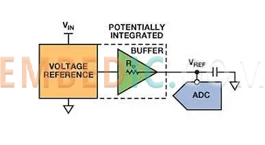
Everyone in the use of microcontroller acquisition of analog signals, often use low-cost program, that is, the use of microcontroller built-in AD module for analog conversion. For products with low accuracy requirements may be able to meet the requirements, but for slightly higher accuracy, and do not want to use external AD conversion chip, then only in the reference port of the microcontroller to add a reference voltage regulator chip, such as TI's REF series reference voltage regulator chip.
Reference voltage regulator chip
Baseline voltage regulator chip schematic
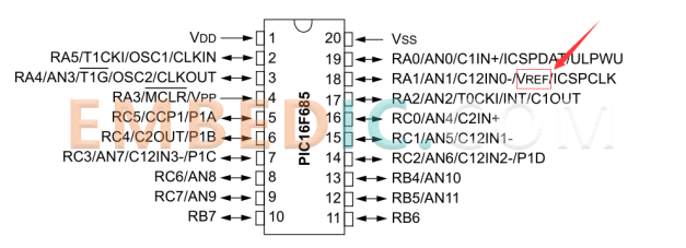
PIC16F685 microcontroller
Here the PIC16F685 MCU as an example, through the pin diagram in the manual can be seen RA1 interface has a function is Vref, this pin function as shown in the figure, where VREF is the ADC reference voltage input pin. In use, we need to connect the output of the reference voltage regulator chip to the RA1 port of the microcontroller, so that the output voltage will be able to provide a reference voltage for the ADC of the microcontroller.
RA1 pin function
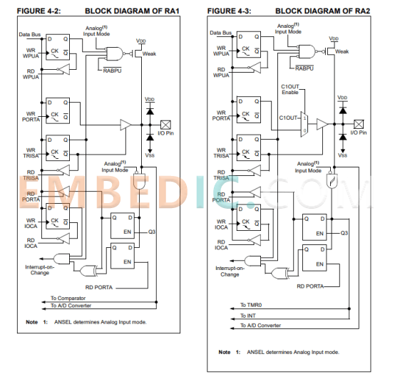
RA1 port function block diagram
The hardware is connected, and the next step is to configure the registers. The ADC function block diagram shows that the ADC reference voltage can be the microcontroller's operating voltage VDD or VREF, and the switch between them is controlled by the register VCFG, so here we need to set the configuration to 1.
VDFG=1;//use VREF as the reference voltage VCFG=0;//use VDD as the reference voltage
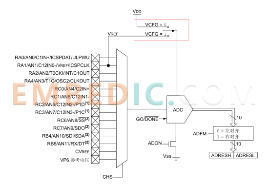
ADC Function Block Diagram
Note: When using VREF as the reference voltage, note that the operating voltage of the microcontroller VDD needs to be greater than VREF, so that the data sampled and converted is accurate and stable, because VDD < VREF, it will make the sampling inaccurate, interested students can also use Proteus software simulation.
// Selecting the internal voltage reference of 2.048V for ADC
FVRCONbits.ADFVR = 0b11;
// Enable Fixed Voltage Reference
FVRCONbits.FVREN = 1;
// Configure ADC module
ADCON0bits.ADON = 1; // Enable ADC module
ADCON1bits.ADCS = 0b110; // Set ADC clock to Fosc/64
ADCON1bits.ADNREF = 0; // Select VREF- as negative reference
ADCON1bits.ADPREF = 0b11; // Select FVR as positive reference
In the above code, the internal reference voltage of 2.048V is selected for the ADC using the Fixed Voltage Reference (FVR) module. The FVR is enabled by setting the FVREN bit to 1.
Next, the ADC module is configured by enabling it using the ADON bit. The ADC clock is set to Fosc/64 using the ADCS bits. The negative reference voltage is set to VREF- using the ADNREF bit, and the positive reference voltage is set to the FVR using the ADPREF bits.
This configuration allows the ADC to convert the analog input signal with respect to the internal reference voltage of 2.048V, resulting in a digital output that accurately represents the analog input signal.
The ADC (Analog-to-Digital Converter) reference voltage of the PIC16F series microcontroller is an important parameter that affects the accuracy of the ADC conversion. The reference voltage determines the range of the input analog signal that can be accurately converted into digital values.
The PIC16F microcontroller offers different options for setting the ADC reference voltage. It can use an internal fixed reference voltage or an external reference voltage. The internal fixed reference voltage is set at 2.048V for most PIC16F devices, but some models may have different values. An external reference voltage can be applied to the VREF+ pin of the microcontroller.
Choosing the appropriate reference voltage for a specific application depends on the desired accuracy and resolution of the ADC conversion. The internal fixed reference voltage is a good option for general-purpose applications, but for more demanding applications, an external reference voltage with higher accuracy and stability may be needed.
In conclusion, the ADC reference voltage of the PIC16F series microcontroller is an important parameter that needs to be carefully selected based on the requirements of the specific application.

Manufacturer: Microchip
IC MCU 8BIT 28KB FLASH 40UQFN
Product Categories: 8bit MCU
Lifecycle:
RoHS:
Manufacturer: Texas Instruments
IC DSP FIX/FLOAT POINT 176HLQFP
Product Categories: DSP
Lifecycle:
RoHS:
Manufacturer: Texas Instruments
IC DGTL MEDIA PROCESSR 1031FCBGA
Product Categories: DSP
Lifecycle:
RoHS:
Manufacturer: Texas Instruments
IC DSP FIX/FLOAT POINT 841FCBGA
Product Categories: DSP
Lifecycle:
RoHS:
Looking forward to your comment
Comment
1
2
3
4
5
6
 Popular Searches
8 Bit MCU, Flash, PIC16 Family PIC16F7XX Series Microcontrollers, 20 MHz, 7 KB, 192 Byte, 44 Pi...
EEPROM 2K 256 X 8 2.5V SERIAL EE IND
System-On-Modules - SOM RCM2200
32-bit Arm Cortex-A53 vision processor with ISP, powerful 3D GPU, dual APEX-2 vision accelerat...
IC MCU 8BIT 60KB FLASH 44QFP
DSP 20MHZ 44QFP
Product updates, events, and resources in your inbox


Smart System

Traffic Management

Security

Consumer Electronics

Wireless Technology

Robot

Internet of Things

Industrial Control


