Hello! Welcome to Embedic!
Arduino is widely familiar to electronics enthusiasts and engineers, but the 8-bit CPU and a clock that is a few beats slower do not lend themselves to deep development. If combined with STM32F103C8T6, a whole new application comes up where we can program the STM32 board on Arduino IDE.
The materials needed for this project are: STM32 Little Blue Pill (STM32F103C8T6), FTDI programmer, breadboard and wires, networkable laptop.
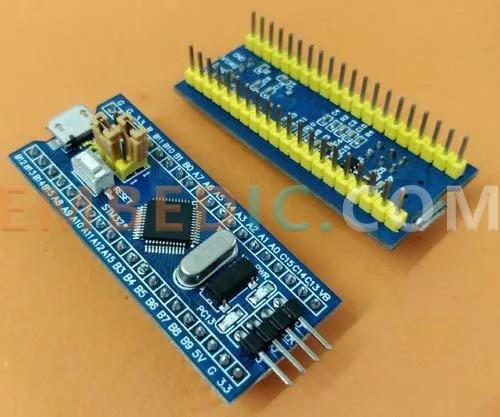
The STM32 development board is called the Little Blue Pill (Blue Pill) due to the blue color of the PCB. It uses the STM32F103C8T6 chip, which is slightly larger than the Arduino Nano board. In addition to the chip itself, the board has an 8Mhz crystal and a 32KHz crystal to drive the internal real-time clock. The board uses 3.3V logic levels, but most of its pins are 5V tolerant and can run in deep sleep mode.
The STM32F103C8T6 is a 32-bit ARM processor running at 72MHz and offers 20KB of RAM and 64KB of flash memory, enough to build large projects. The chip features 37 GPIO pins, 10 ADC pins, SPI, I2C, CAN, UART bus and DMA controller. These impressive chips cost $3. If we compare the specifications of the STM32 with those of the Arduino Uno, we can see that this little board outperforms the Arduino Uno in every area.The STM32 chip operates at 4.5 times the operating frequency of the Arduino Uno. Therefore, the STM32 is expected to be at least 4.5 times faster than the Arduino Uno.
Unlike the Arduino board, the Little Blue Board must be manually reset to programming mode using the boot 1 and boot 0 jumpers, with boot 0 set to 3.3V during programming and ground during operation.
The STM32 board can be programmed using all ARM chip programming methods. some common IDEs are: Keil ARM MDK, IAR workbench, Atollic TrueStudio, MicroC Pro ARM, Crossworks ARM, Ride 7, PlatformIO+STM32. this project uses the Arduino IDE in order to prepare the board for programming. project uses the Arduino IDE for convenience, as people are generally familiar with the Arduino IDE environment.
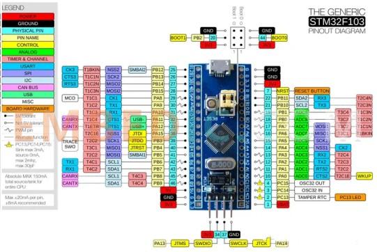
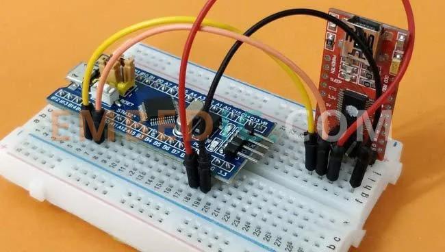
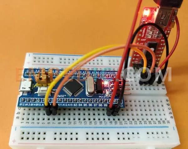
To program the STM32 Blue Pill board directly using Arduino IDE, we need a serial FTDI board, which is connected to the Rx and Tx pins of the small basket board.
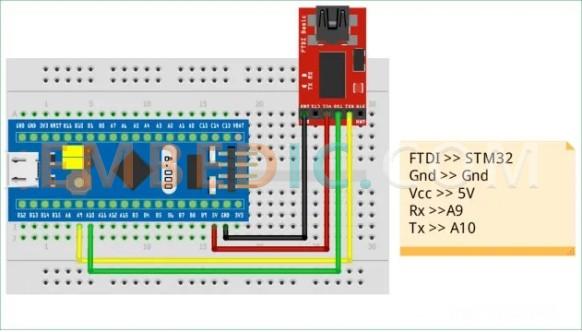
Here, the Vcc pin of the FTDI board is connected to the STM32 5V power supply pin, the ground-ground connection of the two boards, and the Rx and Tx pins are connected to the A9 and A10 pins of the STM32 Small Basket board respectively.
Of course, if it is convenient, you can also directly use the micro-USB port to program the STM32 small basket board, this is to let you know one more way. The steps are as follows:
Step 1:- Select the correct Arduino IDE and install it.
Step 2:- Open Arduino IDE and download the required package for STM32 small basket board.
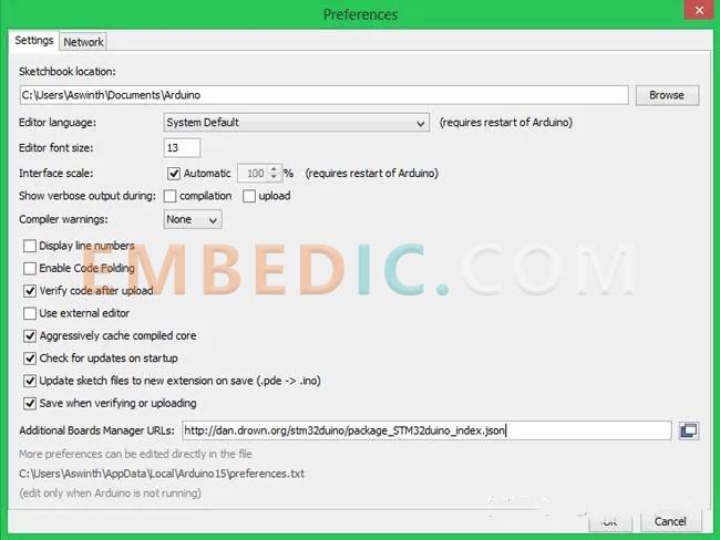
Step 3:- Click on references to open the following dialog box, paste the link in the Boards Manager URL text box and press OK.
Step 4:- Go to Tool -> Boards -> Board Manager to open the Board Manager and select "STM32F1", then install the package that appears.
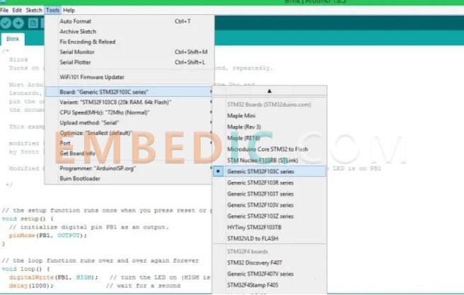
Step 5:- Installation is complete. In the Tools drop down, look for Generic STM32F103C series as below, make sure the parameters are: 64kFlah type, CPU speed is 72MHz, and change the upload mode to serial port.
Step 6:- Link the FTDI board to your computer and check which COM port the FTDI board is connected to is used for device management. Then, select the same port number in Tools->Port.
Step 7:- After completing the above changes, check the bottom right corner of the Arduino IDE to show that it is being set up. With this, the Arduino IDE is ready to program the STM 32 small basket board.
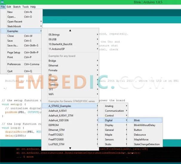
Upload the Sample Blink Program from the Arduino IDE to the STM32 Small Basket Board and make sure it is running correctly.
Once the Sample Program is open, small changes need to be made. The default shape is written to PB1, the LED in this project is connected to PC13, which needs to be used instead of PB1.
Since we are well on our way, make a note that the following program appears so that the LED will blink at 1000 ms intervals.
digitalWrite(PC13, HIGH); // turn the LED on (HIGH is the voltage level)
delay(1000); // wait for a second
digitalWrite(PC13, LOW); // turn the LED off by making the voltage LOW
delay(1000); // wait for a second
Since earlier STM32 boards had to be set to programming mode before uploading the program, this required the boot 0 jumper to be set low.
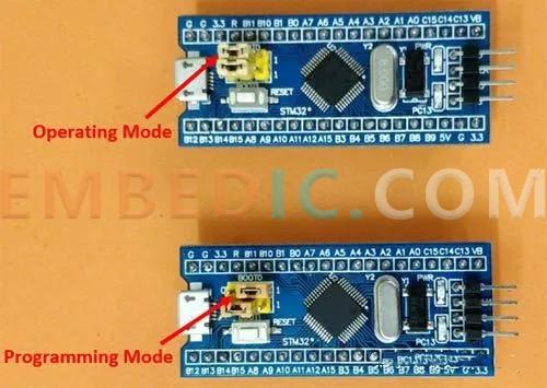
Now, press the reset button to enter programming mode, the green LED etc. goes off to indicate that the board is ready.
Press the Arduino IDE's Upload Ken to start programming and uploading. If all is well, the Arduino IDE interface will appear.
After the program is uploaded normally, the green LED will blink at 1-myth intervals, of course, you can also change the program to increase or shorten the time interval to achieve different effects of blinking experience.
After the program is uploaded, the boot 0 jumper should be reset to run mode, so that the next time the board is powered on it will automatically start uploading the program.
Attachment: STM32 blinking code
/*
Circuit Digest
Sample STM32 Blink Program for Blue Pill board
*/
// the setup function runs once when you press reset or power the board
void setup() {
// Initialize digital pin PC13 as an output.
pinMode(PC13, OUTPUT); // initialize digital pin PC13 as an output. pinMode(PC13, OUTPUT); }
pinMode(PC13, OUTPUT); }
// the loop function runs over and over again forever
digitalWrite(PC13, HIGH); } // the loop function runs over and over again forever. void loop() {
digitalWrite(PC13, HIGH); // turn the LED on (HIGH is the voltage level)
delay(1000); // wait for a second
digitalWrite(PC13, LOW); // turn the LED off by making the voltage LOW
delay(1000); // wait for a second
}

Manufacturer: Texas Instruments
IC DSP FIX/FLOAT POINT 625FCBGA
Product Categories: DSP
Lifecycle:
RoHS:
Manufacturer: Texas Instruments
IC DGTL MEDIA PROCESSOR 529FCBGA
Product Categories: DSP
Lifecycle:
RoHS:
Manufacturer: Texas Instruments
IC DGTL MEDIA PROCESSOR 529FCBGA
Product Categories: DSP
Lifecycle:
RoHS:
Manufacturer: Texas Instruments
IC DGTL MEDIA PROCESSOR 529FCBGA
Product Categories: DSP
Lifecycle:
RoHS:
Looking forward to your comment
Comment
1
2
3
4
5
6
 Popular Searches
8 Bit MCU, Flash, PIC16 Family PIC16F7XX Series Microcontrollers, 20 MHz, 7 KB, 192 Byte, 44 Pi...
EEPROM 2K 256 X 8 2.5V SERIAL EE IND
System-On-Modules - SOM RCM2200
32-bit Arm Cortex-A53 vision processor with ISP, powerful 3D GPU, dual APEX-2 vision accelerat...
IC MCU 8BIT 60KB FLASH 44QFP
DSP 20MHZ 44QFP
Product updates, events, and resources in your inbox


Smart System

Traffic Management

Security

Consumer Electronics

Wireless Technology

Robot

Internet of Things

Industrial Control


