Hello! Welcome to Embedic!
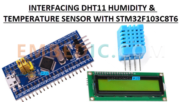
In this tutorial I will describe how to interface the DHT11 humidity and temperature sensors with the STM32 Blue Pill Board based on the STM32F103C8T6 MCU. The values of the DHT11 sensors are read by the STM32 and displayed on the I2C LCD display.
Sensors are very small devices that bridge the gap between the raw analog world and the digital world of the MCU. Sensors can be very simple, such as the very famous LM35 temperature sensor, or they can be some complex mathematical unit, such as the MPU6050 gyroscope and accelerometer combination sensor.
Simple or complex, sensors are a key part of many consumer, automotive, robotics and industrial applications and some applications cannot be accomplished without integrating the proper sensors.
Let's expand from industrial applications to everyday projects and hobbyists. Weather stations are a very common and popular project for both IoT applications and regular character LCD applications.
The key component of such weather station projects is the ability to detect weather related parameters (such as temperature, humidity, etc.) The DHT11 humidity and temperature sensor is the device for these types of projects.
I have used the DHT11 sensor in an Arduino project called " DHT11 Humidity Sensor on Arduino" (first tweet). In that project, I have interfaced the DHT11 sensor with the Arduino, calculated the temperature and humidity values and displayed them on a 16×2 LCD display. I will do the same thing here, but this time I will interface the DHT11 humidity and temperature sensors to the STM32F103C8T6 MCU.
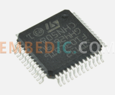
The STM32F103C8T6 is a 32-bit ARM Cortex-M3 based microcontroller with 64 KB of Flash memory, 20 KB of SRAM, a range of built-in peripherals, and support for various communication interfaces, making it a versatile choice for embedded applications.
The DHT11 and its brother, the DHT22, are inexpensive but highly reliable humidity and temperature sensors.The DHT22's range and accuracy are slightly better than the DHT11's, but this extended range and tighter accuracy comes at a price. On top of that, both sensors look similar and have the same pins and connectivity. Therefore, from now on, we will focus on the sensor for this project, the DHT11.
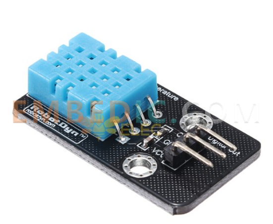
It is an ultra-low-cost sensor with a resistive humidity measurement component, an NTC-type temperature measurement component and an 8-bit microcontroller that converts the data from the two measurement components into digital values.
In the Arduino - DHT11 tutorial, I talked about how the sensor works and how to interpret the data from the serial. I recommend that you refer to that project for more information about this sensor.
Also, in that project I didn't use any dedicated libraries for the DHT11 humidity and temperature sensors, but tried my own code. For changes only, I will use the DHT library developed by Adafruit.
Connecting the DHT11 Humidity and Temperature Sensor to the STM32F103C8T6
Before proceeding, I must remind you of something in the DHT11 sensor datasheet. It says that the single data line between the DHT11 sensor and the microcontroller (STM32 in this case) must be pulled up with the help of a 5KΩ resistor.
Therefore, when purchasing a DHT11 sensor, try to buy a module that includes the said pull-up resistor (or even some energized LEDs). This makes connecting the DHT11 humidity and temperature sensors to the STM32F103C8T6 much easier as it does not require any other components.
Another thing to keep in mind is that I used an I2C LCD, i.e. an I2C GPIO expander module based on the PCF8574 module with a good old 16×2 LCD display. I have already implemented the same functionality in the dedicated project "Interfacing I2C LCD with STM32F103C8T6". Please refer to that project for more information.
First, connect the VCC and GND pins of the DHT11 Sensor to + 5V and GND respectively. then connect the data pin of the sensor to pin PA1 of the STM32 board.
When you come to the LCD, insert the PCF8574 I2C LCD module into the back of the LCD and connect the SDA and SCL pins of the PCF8574 module to pins PB7 and PB6 of the STM32 board, respectively. Similarly, connect the VCC and GND pins of the I2C LCD module to + 5V and GND.
Programming the STM32 to connect the DHT11
Before proceeding, make sure you have identified the slave address of the PCF8574 module mentioned in the I2C LCD tutorial. You can use the following code for the same.
#include
void setup()
{
Wire.begin();
Serial.begin(9600);
while (!Serial); }
}
void loop()
} void loop(); } void loop(); } void loop()
byte error, address; int I2CDevices.
int I2CDevices.
Serial.println("Scanning for I2C Devices...");
I2CDevices = 0; for (address = 1; address < 127; address < 0)
for (address = 1; address < 127; address++ )
{
Wire.beginTransmission(address); error = Wire.endTransmission(address); }
error = Wire.endTransmission(); if (error == 0); I2CDevices = 0; for I2C Devices.
if (error == 0)
error = Wire.endTransmission(); if (error == 0) {
Serial.print("I2C device found at address 0x"); if (address < 16)
if (address < 16)
Serial.print("0″); if (address < 16)
Serial.print(address, HEX); Serial.println("!
Serial.println(" !"); if (address < 16) Serial.print(address, HEX); Serial.println(" !") ;
I2CDevices++;
}
else if (error == 4)
} else if (error == 4)
Serial.print("Unknown error at address 0x"); if (address < 16); } else
Serial.print("Unknown error at address 0x"); if (address < 16)
Serial.print("0"); Serial.println(address, HEX); if (address < 16)
Serial.println(address, HEX);
}
}
Serial.println(address, HEX); } } if (I2CDevices == 0)
Serial.println("No I2C devices found "); } if (I2CDevices == 0)
Serial.println("No I2C devices found "); }
Serial.println("**** ");
Serial.println(" "); delay(5000);
}
Now for the actual program ahead, start by downloading the DHT library from this link. Unzip the zip file and copy its contents to the library folder of your local Arduino installation. The path is usually " C: Program Files (x86) Arduino libraries".
Then, in the program, define the data pin of the DHT as PA1 and the type of the DHT sensor as DHT11 or DHT22. Declare the I2C LCD with the LiquidCrystal_I2C library functionality by mentioning the slave address, the number of columns and the number of rows. Now you can initialize the LCD and the DHT11 sensor using the respective "Start" function.
Now, get the two floating point values and get the humidity and temperature readings from the sensors. Finally, print these values on the LCD.
Source Code
#include
#include
#include
#define DHTPIN PA1
#define DHTTYPE DHT11
LiquidCrystal_I2C lcd(0x27, 16, 2);
DHT dht(DHTPIN, DHTTYPE);
byte degree_symbol[8] =
{
0b00111,
0b00101,
0b00111,
0b00000,
0b00000,
0b00000,
0b00000,
0b00000
};
void setup()
{
lcd.begin();
dht.begin();
lcd.backlight();
lcd.setCursor(0,0);
lcd.print(“Electronics Hub”);
lcd.setCursor(0,1);
lcd.print(“DHT11 with STM32”);
delay(2000);
lcd.clear();
lcd.setCursor(0,0);
lcd.print(“Temp = “);
lcd.setCursor(0,1);
lcd.print(“Humid = “);
lcd.createChar(0, degree_symbol);
lcd.setCursor(12,0);
lcd.write(0);
lcd.print(“C”);
lcd.setCursor(14,1);
lcd.print(“%”);
}
void loop()
{
float hum = dht.readHumidity();
float tem = dht.readTemperature();
lcd.setCursor(7,0);
lcd.print(tem);
lcd.setCursor(8,1);
lcd.print(hum);
}
Conclusion
A simple project has been implemented here to demonstrate the interface of the DHT11 humidity and temperature sensors with the STM32 Blue Pill Board based on the STM32F103C8T6 MCU.

Manufacturer: Texas Instruments
IC DSP FIX/FLOAT POINT 625FCBGA
Product Categories: DSP
Lifecycle:
RoHS:
Manufacturer: Texas Instruments
IC DGTL MEDIA PROCESSOR 529FCBGA
Product Categories: DSP
Lifecycle:
RoHS:
Manufacturer: Texas Instruments
IC DGTL MEDIA PROCESSOR 529FCBGA
Product Categories: DSP
Lifecycle:
RoHS:
Manufacturer: Texas Instruments
IC DGTL MEDIA PROCESSOR 529FCBGA
Product Categories: DSP
Lifecycle:
RoHS:
Looking forward to your comment
Comment
1
2
3
4
5
6
 Popular Searches
8 Bit MCU, Flash, PIC16 Family PIC16F7XX Series Microcontrollers, 20 MHz, 7 KB, 192 Byte, 44 Pi...
EEPROM 2K 256 X 8 2.5V SERIAL EE IND
System-On-Modules - SOM RCM2200
32-bit Arm Cortex-A53 vision processor with ISP, powerful 3D GPU, dual APEX-2 vision accelerat...
IC MCU 8BIT 60KB FLASH 44QFP
DSP 20MHZ 44QFP
Product updates, events, and resources in your inbox


Smart System

Traffic Management

Security

Consumer Electronics

Wireless Technology

Robot

Internet of Things

Industrial Control