Hello! Welcome to Embedic!
Access control system is one of the very important security control systems in modern society, and its function is to provide convenience for legitimate users while safeguarding the security of buildings. The current design of an access control system design scheme based on STM32+RC522 realizes the registration, identification and identity verification of user cards through RFID-RC522 module, and the opening and closing of door locks by controlling SG90 servo, which has high security and reliability. The experimental results show that the access control system can effectively guarantee the security of the building.
Access control systems are widely used in various buildings, enterprises and institutions to manage the entry and exit of personnel, control the range of personnel activities, and achieve security monitoring and other functions. Traditional access control systems use password input or swipe cards for identity verification, but there is a risk that they can be easily cracked. RFID-based access control systems have become a relatively advanced security control scheme.
The STM32+RC522 access control system designed here completes the identification by registering and identifying the user's card through the RFID-RC522 module to switch on and off the door lock. The system comes with OLED display, and after entering the user password and logging in, new cards can be registered, new cards added, and unused cards can be cancelled. In the system, IC card data are stored in the internal sector of the card and managed through the internal space of the card.
Version with 5V-step motor:
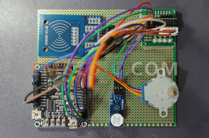
The access control system consists of STM32F103C8T6 microcontroller, RFID-RC522 module, SG90 servo, LCD1602 LCD, and keyboard module. Among them, STM32F103C8T6 MCU is used as the core controller of the system to control the execution of the program; RFID-RC522 module is used as the device to identify the user's card; SG90 servo is used as the door lock control device; OLED display provides the user input information and the display of system information; keyboard module facilitates the user to input the password and card information.
【1】RFID card information management
This system uses the internal space of the card for IC card information management. Each IC card can be divided into multiple sectors, each sector contains multiple blocks, each block contains 16 bytes. Sector 0 is already reserved by the manufacturer for storing the serial number of the card, and sectors 1-15 can be configured by users themselves for storing some private data, such as user identity, license plate number, employee number, etc.
In this system, the management of IC card information mainly includes three aspects: new card registration, card identification and card cancellation.
For the registration of the new card, the user needs to press the "#" key on the keyboard to enter the registration mode, then enter the administrator password, then put the new card on the RFID reader, the system will read the card serial number and store the user name and password information in the sector of the card.
For card identification, when the user presses the confirmation button of the access control system, the system will read the card serial number read in the RFID module and go to the card sector to query the user name and password information for identity verification. If the card identification is successful, the system will control the servo to rotate one turn to achieve the unlocking function.
For the cancellation of the card, the administrator needs to enter the password for identity verification, and then to cancel the card to the RFID reader, the system will clear all the data in the sector of the card.
【2】 Access control system security control
The access control system uses a combination of password verification and card identification to improve the security of the system. Specifically, the system requires the user to enter a password or swipe the card for identity verification, and only after successful verification can control the door lock for opening and closing operations. At the same time, the system can also record the time and user information of each time the door lock is opened, so that the administrator can monitor the security.
【3】 Door lock control
This access control system uses SG90 servo to control the door lock switch, which has the advantages of simple structure and convenient control. In the door lock control process, the system provides fine control of the frequency and duty cycle of the servo control signal to achieve accurate switching of the door lock.
【1】STM32F103C8T6 microcontroller
STM32F103C8T6 microcontroller is a programmable 32-bit microcontroller based on Cortex-M3 core from ST, which is often widely used in industrial control, smart home, embedded control and other fields.
Its main features include:
【2】RFID-RC522 Module
RFID-RC522 module is a low-cost, cost-effective RFID reader module. It has the characteristics of high accuracy and fast reading, and is widely used in access control system, smart card management, logistics tracking and other fields.
The features of RFID-RC522 module are as follows:
The RFID-RC522 module needs to be used with related library files to write code and develop on Arduino, Raspberry Pi and other development boards. Common use scenarios include access control systems, smart card management, access control, logistics tracking and other fields.
【3】SG90 Servo
This servo is small and durable, and can precisely control the opening and closing of the door lock.
SG90 servo is a small servo with small size, light weight and low price, which is often used in model airplanes, small robotic arms, toy models and other fields. It uses a DC motor, PID control technology, and a precision pinion gearbox to achieve steering angle control.
The features of SG90 servo are as follows:
【4】0.96 inch OLED display
0.96 inch SPI interface OLED display is a miniaturized screen, belongs to OLED display technology, using SPI interface connection, the appearance size is about 12mm * 12mm, the resolution is generally 128 * 64 or 128 * 32. it can be used in a variety of small electronic devices, such as handheld devices, small instruments, smart home control panel and so on.
OLED is organic light-emitting diode, compared with the traditional liquid crystal display, OLED has a fast response time, a wide range of viewing angles, bright colors, high brightness and other advantages. SPI interface is a serial peripheral interface, with simple, flexible, high-speed characteristics.
0.96 inch SPI interface OLED display driver chip is generally SSD1306, there are 128 columns and 64 rows of pixels, and some have 128 columns and 32 rows of pixels. Among them, the 128 * 64 pixels screen display area is larger and more clear and detailed when displaying images and text. 0.96 inch SPI interface OLED display has the advantages of small size, high definition and high speed, and is widely used in various small electronic devices.
【5】Keypad Module
This module allows easy input of passwords and card information.
The IIC interface 4x4 capacitive matrix keyboard module is a capacitive keypad module based on IIC bus communication, which is often used in industrial control, home appliances, medical devices and other fields.
Its main features include:
The IIC interface 4x4 capacitive matrix keypad module is a convenient and easy-to-use, high-sensitivity keypad module that enables key detection and response through capacitive key design, and simplifies the connection through IIC bus communication. It is suitable for applications in many fields, such as industrial control, home appliances and medical devices, and can bring a more convenient and efficient way to control the user's products.
The following code is based on GPIO analog timing to control the STM32F103C8T6 to drive the SG90 servo to rotate a specified angle and encapsulate it into sub-function calls.
#include "stm32f10x.h"
#include "stm32f10x_gpio.h"
#include "stm32f10x_rcc.h"
#include "delay.h"
#define Servo_pin GPIO_Pin_5
#define Servo_port GPIOA
void SG90_Init(void)
{
RCC_APB2PeriphClockCmd(RCC_APB2Periph_GPIOA, ENABLE);
GPIO_InitTypeDef GPIO_InitStructure;
GPIO_InitStructure.GPIO_Pin = Servo_pin;
GPIO_InitStructure.GPIO_Mode = GPIO_Mode_Out_PP;
GPIO_InitStructure.GPIO_Speed = GPIO_Speed_50MHz;
GPIO_Init(Servo_port, &GPIO_InitStructure);
}
void SG90_SetAngle(uint8_t angle)
{
if(angle>180) angle=180;
if(angle<0) angle = 0;
uint8_t temp = angle/2 + 15;
for(int i=0;i<5;i++)
{
GPIO_SetBits(Servo_port, Servo_pin);
delay_us(temp);
GPIO_ResetBits(Servo_port, Servo_pin);
delay_us(20000-temp);
}
}
int main(void)
{
SystemInit();
delay_init();
SG90_Init();
while(1)
{
for(int i=0;i<=180;i+=10)
{
SG90_SetAngle(i);
delay_ms(500);
}
}
}
Among them, SG90_Init() function is used to initialize the PA5 port and configure it to output mode.
The SG90_SetAngle() function is used to drive the servo to rotate to the specified angle. In this function, the delay time temp (in microseconds) is first calculated based on the given angle value, and then the GPIO port is used to control the SG90 servo to output high during the temp delay time and low for the rest of the time. By adjusting the delay time and distributing the pulse width by angle, the purpose of driving the SG90 servo to rotate is achieved.
The for loop in the main() function controls the rotation of the servo from 0 degrees to 180 degrees. The code uses the delay_init() function and the delay_ms() and delay_us() functions. They are self-written delay functions that can achieve millisecond and microsecond level delays, and the specific code is as follows:
#include "stm32f10x.h"
void delay_init(void)
{
if (SysTick_Config(SystemCoreClock / 1000000)){
while(1);
}
}
static __IO uint32_t delay_us_tick;
void delay_us(uint32_t nUs)
{
delay_us_tick = nUs;
while (delay_us_tick);
}
static __IO uint32_t delay_ms_tick;
void delay_ms(uint32_t nMs)
{
delay_ms_tick = nMs;
while (delay_ms_tick);
}
void SysTick_Handler(void)
{
if (delay_us_tick > 0){
delay_us_tick--;
}
if (delay_ms_tick > 0){
delay_ms_tick--;
}
}
Among them, the delay_init() function is used to configure the system clock source and SysTick timer to realize the function of generating an interrupt for each SysTick clock. delay_us() and delay_ms() functions are used to realize the microsecond level and millisecond level delay, respectively, by limiting the value of delay_us_tick and delay_ms_tick to realize the effect of delay. SysTick_Handler() is an interrupt handling function, each time the SysTick timer count is decremented by 1, when it reaches 0, the corresponding delay_us_tick or delay_ms_tick is also decremented by 1, and the delay is achieved by waiting for the value to be 0 in a loop.
In the SG90_SetAngle() function in the code, it is necessary to precisely control the level time of GPIO to make it generate the corresponding pulse width to control the servo rotation angle. Therefore, it is necessary to configure the output mode and speed of GPIO port, set the level time calculated according to the angle in the delay_us() function, so that the servo can execute the rotation accurately.
The following is a code example to control the STM32F103C8T6 based on SPI interface to drive the RFID-RC522 module to complete card identification and sector read/write. In this code, the SPI1 interface is used and the RFID-RC522 module is connected to the STM32F103C8T6 through the SPI1 interface.
The code implements the function of reading card information and completing sector read/write by encapsulating SPI related operations and MFRC522 library functions.
#include "stm32f10x.h"
#include "stm32f10x_spi.h"
#include "stm32f10x_gpio.h"
#include "stm32f10x_rcc.h"
#include "delay.h"
#include "mfrc522.h"
#include "stdio.h"
#define SPI_CE_LOW() GPIO_ResetBits(GPIOA,GPIO_Pin_4)
#define SPI_CE_HIGH() GPIO_SetBits(GPIOA,GPIO_Pin_4)
void SPI1_Init(void)
{
RCC_APB2PeriphClockCmd(RCC_APB2Periph_GPIOA, ENABLE);
RCC_APB2PeriphClockCmd(RCC_APB2Periph_SPI1, ENABLE);
GPIO_InitTypeDef GPIO_InitStructure;
GPIO_InitStructure.GPIO_Pin = GPIO_Pin_5 | GPIO_Pin_6 | GPIO_Pin_7;
GPIO_InitStructure.GPIO_Mode = GPIO_Mode_AF_PP;
GPIO_InitStructure.GPIO_Speed = GPIO_Speed_50MHz;
GPIO_Init(GPIOA, &GPIO_InitStructure);
GPIO_InitStructure.GPIO_Pin = GPIO_Pin_4;
GPIO_InitStructure.GPIO_Mode = GPIO_Mode_Out_PP;
GPIO_InitStructure.GPIO_Speed = GPIO_Speed_50MHz;
GPIO_Init(GPIOA, &GPIO_InitStructure);
SPI_InitTypeDef SPI_InitStructure;
SPI_InitStructure.SPI_Direction = SPI_Direction_2Lines_FullDuplex;
SPI_InitStructure.SPI_Mode = SPI_Mode_Master;
SPI_InitStructure.SPI_DataSize = SPI_DataSize_8b;
SPI_InitStructure.SPI_CPOL = SPI_CPOL_High;
SPI_InitStructure.SPI_CPHA = SPI_CPHA_2Edge;
SPI_InitStructure.SPI_NSS = SPI_NSS_Soft;
SPI_InitStructure.SPI_BaudRatePrescaler = SPI_BaudRatePrescaler_2;
SPI_InitStructure.SPI_FirstBit = SPI_FirstBit_MSB;
SPI_InitStructure.SPI_CRCPolynomial = 7;
SPI_Init(SPI1, &SPI_InitStructure);
SPI_Cmd(SPI1, ENABLE);
}
uint8_t SPI1_SendByte(uint8_t byte)
{
while(SPI_I2S_GetFlagStatus(SPI1, SPI_I2S_FLAG_TXE) == RESET);
SPI_I2S_SendData(SPI1, byte);
while(SPI_I2S_GetFlagStatus(SPI1, SPI_I2S_FLAG_RXNE) ==
RESET); return SPI_I2S_ReceiveData(SPI1); }
void MFRC522_Reset(void) { SPI_CE_LOW(); SPI1_SendByte(0x1B); SPI_CE_HIGH(); }
uint8_t MFRC522_ReadRegister(uint8_t addr) { SPI_CE_LOW(); uint8_t data; SPI1_SendByte(0x80 | addr); data = SPI1_SendByte(0x00); SPI_CE_HIGH(); return data; }
void MFRC522_WriteRegister(uint8_t addr, uint8_t val) { SPI_CE_LOW(); SPI1_SendByte(0x7F & addr); SPI1_SendByte(val); SPI_CE_HIGH(); }
void MFRC522_ReadRegisters(uint8_t addr, uint8_t count, uint8_t *values) { SPI_CE_LOW(); SPI1_SendByte(0x80 | addr); for(uint8_t i=0;i;i++)>
Manufacturer: Texas Instruments
IC DSP FIX/FLOAT POINT 176HLQFP
Product Categories: DSP
Lifecycle:
RoHS:
Manufacturer: Microchip
IC MCU 8BIT 1.75KB FLASH 18DIP
Product Categories: 8bit MCU
Lifecycle:
RoHS:
Manufacturer: Texas Instruments
IC DSP FIX/FLOAT POINT 256BGA
Product Categories: DSP
Lifecycle:
RoHS:
Manufacturer: Texas Instruments
IC DGTL MEDIA PROCESSR 684FCBGA
Product Categories: DSP
Lifecycle:
RoHS:
Looking forward to your comment
Comment
1
2
3
4
5
6
 Popular Searches
8 Bit MCU, Flash, PIC16 Family PIC16F7XX Series Microcontrollers, 20 MHz, 7 KB, 192 Byte, 44 Pi...
EEPROM 2K 256 X 8 2.5V SERIAL EE IND
System-On-Modules - SOM RCM2200
32-bit Arm Cortex-A53 vision processor with ISP, powerful 3D GPU, dual APEX-2 vision accelerat...
IC MCU 8BIT 60KB FLASH 44QFP
DSP 20MHZ 44QFP
Product updates, events, and resources in your inbox


Smart System

Traffic Management

Security

Consumer Electronics

Wireless Technology

Robot

Internet of Things

Industrial Control


