Hello! Welcome to Embedic!
1/8w 4.7k 6 (6 in total)
560r 3 (3 in total)
2k2 1
4.7 ohm 1 is connected in series with the power supply circuit for protection
10k exclusion 1 for cpu p0 port pull-up
1n4148 2 is used for vpp high voltage supply (note that one end of 4148 is black)
12v 1 is used for vpp high voltage supply (note that the end of 12V is white, don't confuse it)
4.7uf/50v 8 All electrolysis uses the same model, pay attention to the direction
104 2 For power supply filtering
22p 2 for crystal circuit
11.0592 1 crystal
2n5401 1 Pay attention to the model and the direction of insertion, make no mistake!
2n5551 2
LED 2 3mm white hair red (used for power indication and communication indication) (note the direction)
db9 1 serial port header
20pin deck 1 for programming 2051 etc.
40pin ic socket 1 plug-in monitoring 89s51
16pin ic socket 1 insert max232 chip
usb socket 1 for power supply
Serial cable 1 For communication
usb cable 1 for power supply
At89s51 1 for monitoring
max232cpe 1 Integrated circuit for communication
pcb 1 circuit board
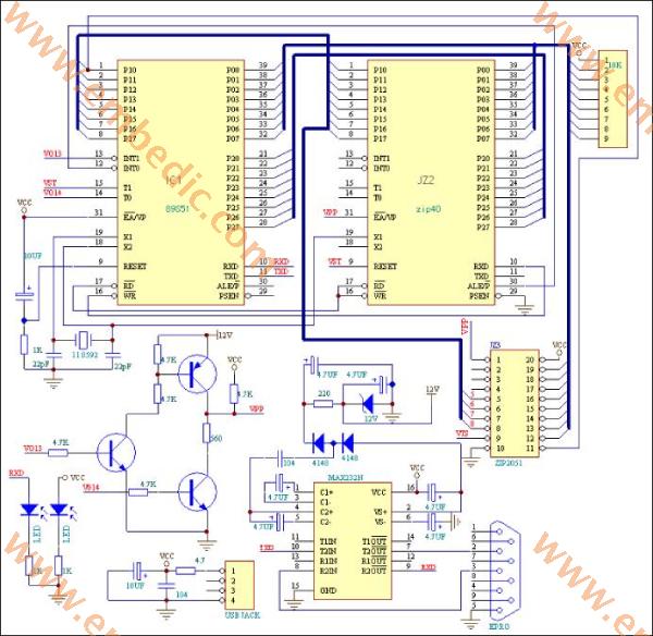
Now the AT89C2051 Microcontroller has been prepared in advance, and then I will explain the debugging methods and steps in detail:
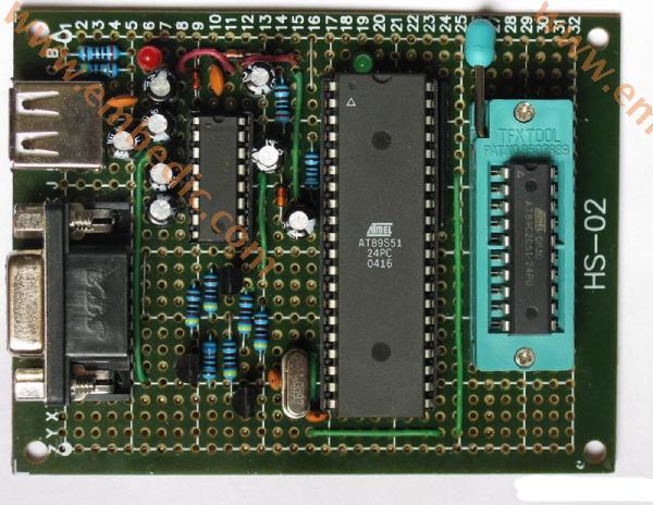
This circuit may be a bit more complicated for beginners. It is divided into several parts. If you plan the AT89C2051 Architecture first, then solder the components all at once, and then debug, the probability of success is very small. What should I do? First plan the location and layout of the components, and then divide them into several units. After one unit is completed, debug it, and then proceed to the next unit after it is normal. My plan is as follows, first the power supply part includes the power indicator LED:
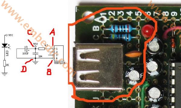
First solder the USB socket, confirm that there is no short circuit in the AT89C2051 Architecture, and then plug in the USB power supply. Use a multimeter to find out which of the points A and B is the 5V positive pole and which is the ground. Then remove the power supply and solder the remaining capacitors, resistors and LEDs. After confirming that there is no short circuit, connect the power supply and the LED should light up. I changed the current limiting resistor of the LED to 2K, because I think it is bright enough. The current is 1.5 mA. The real object is the picture circled in red on the right.
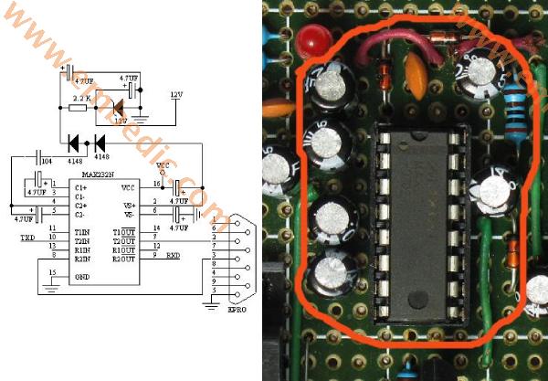
The second part is MAX232, including that +12v voltage regulator circuit. MAX232 is a dedicated IC for TTL to RS232. It provides a positive 10v and negative 10v boost circuit inside. We just used its boost circuit to obtain a +12v power supply.
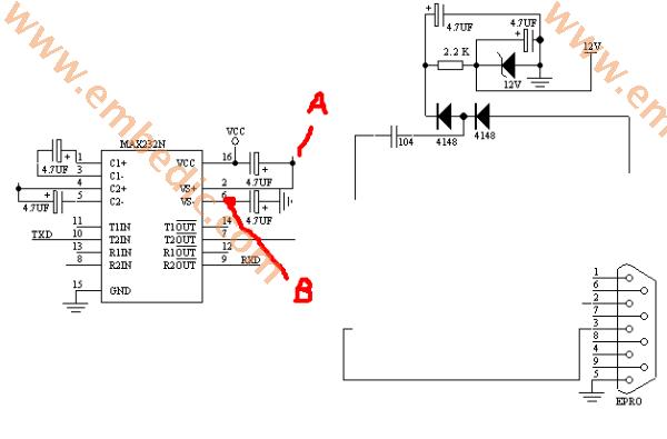
We first soldered the 9-pin serial port, but did not connect to MAX232. In your planned MAX232 area, weld the MAX232 seat and four capacitors according to the circuit on the left side of the figure above. After checking that there is no short circuit, plug in MAX232 and connect to the power supply. The voltage of +9v-+10v should be measured at point A. There should be a voltage of -9v-10v at point B. Connect pin 10 to ground, and pin 7 should be +10V. If pin 10 is connected to +5v, then pin 7 becomes -10v. So MAX232 is normal. Connect pin 2 of the serial port to pin 7 of MAX232. Pin 3 of the serial port is connected to Pin 8 of MAX232. Connect the power to the 10 pins of MAX232 to ground and +5v respectively to see if the 2 pins of the serial port change as before. After the above debugging is correct, solder the 12V voltage regulator circuit on the right side of the above figure. As shown below:
Use a multimeter to measure a stable +12V voltage across the regulator tube. In this way, your serial port conversion and 12v power supply circuit will be debugged normally.
The third part is the 12V programming control part: AT89C2051 Programmer circuit and physical diagram are as follows:
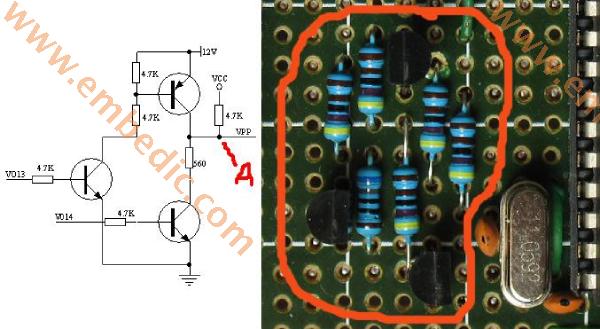
After this part of the circuit is welded, connect the +12v and power supply +5V that are debugged normally in the second part. First measure whether the +12v access point and the power supply voltage +5v on the circuit are normal. Then measure the point A in the above figure should also be +5v. Then you connect VO13 to +5V with a wire, then point A is +9v-+11v. it is good! Disconnect VO13, and then connect V014 to +5v with a wire. Point A should be close to 0. In this way, the 12V programming control circuit is also debugged correctly.
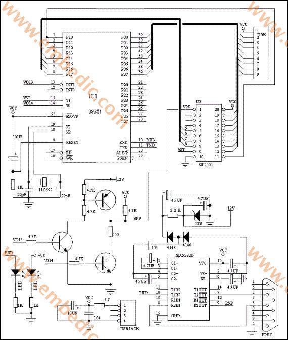
The following is the circuit of S51 part, as shown in the figure below:
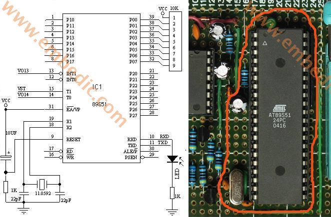
This part of the circuit includes the pull-up resistor of port P0 and the receiving indicator LED connected to pin 10 of S51. Don't forget to connect pin 31 (EA / VP) of S51 to +5v. First make sure to disconnect the connection between the 9th pin of MAX232 and the 10th pin of S51 (because MAX232 outputs +5v high level on 9th pin after the debugging is normal, which will light up the receiving indicator LED, which hinders the inspection of S51 performance). After checking that the circuit is correct, plug in the S51 chip and connect to the power supply. The quiescent current should be around 9-12mA. it is good! Open KEIL and write a test program:
#include <AT89X51.H>
#define uchar unsigned char
main(void)
{
uchar i,j,k;
while(1)
{
for(i=0;i<1;i++)
{
for(j=0;j<255;j++)
for(k=0;k<255;k++);
}
P3_0=~P3_0;
}
}
This program is to make the LED connected to pin 10 (P3.0) of S51 blink. Flashing means that the crystal oscillator starts to vibrate, the S51 circuit is working normally, compile it, and then use the ISP to write this program into the S51 chip, and then plug it into our 2051 programmer. Connected to the power supply, my AT89C2051 circuit immediately worked normally, and the LED was flashing. If the LED does not respond, you have to check whether your S51 circuit is connected properly, whether the crystal oscillator is soldered correctly, etc.
After the S51 circuit is normal, we will solder the 9th pin of MAX232 and the 10th pin of S51 that we just disconnected. At this time, we will compile a test program:
#include<at89x51.h>
#include<stdio.h>
void main(void)
{
SCON=0x50;
TMOD=0x20;
PCON=0x80;
TCON=0x40;
TH1=0xfd;//bit rate 19200
TL1=0xfd;
TI=1;
TR1=1;
while(1)
{
printf("hello World!\n");
}
}
This program is to open the serial port of the MCU S51 and continuously send out the string "hello World". Compile it into a HEX file, and then use ISP to write the program into the S51 chip. Then plug it into the 2051 programming board. Connect the serial cable to the PC. Turn on the PC and run the serial port debugger:
Set the baud rate of the position drawn by the red circle to 19200. Confirmed as COM1 port. Then turn on the power of the 2051 programmer, and "Hello World" immediately appeared on my PC serial debugger.
In this way, the serial communication with the PC is successfully debugged. If you do not have the correct result, and the above steps of debugging are normal, then there is an error in the wiring from the PC serial port to your S51. Check your wiring carefully and you will find the error.
After the above steps are normal, the circuit that has been debugged in these steps is integrated. Connect the 12v programming control terminal VPP to the first pin of 2051, and connect VO13 and VO14 to the 13th and 14th pins of S51 respectively. The 15th pin VST of S51 is connected to the 9th pin of 2051. The first pin (P1.0) of S51 is connected to the 11th pin of 2051. S51's 5, 6, 7, and 8 are connected to the 5th, 6th, 7th, and 8th pins of 2051 respectively. Port P0 (pins 32-39) of S51 is connected to pins 12-19 of seat 2051. Don't forget to connect the 2051 power supply to the ground.
After checking that it is correct, connect the power supply and try again if the serial port communication is normal (to prevent the S51 from working after welding by mistake). Unplug S51, use ISP to write the driver firmware of E51Pro.HEX into S51, then plug it into the 40-pin S51 socket, plug AT89C2051 into the 20-pin IC socket, connect the PC serial port, and run the Easy 51Pro on the PC V2.0, then power on the 2051 writer. First select AT89C2051 on the PC software, click the detection device, my, 1e 21 FF. Then try to open a HEX file, click Auto complete, it will complete the device detection, erasing, writing, verification, etc. all the way.
If your device is not found, but the previous serial communication and other debugging are normal, then the wiring in the last step may be wrong. Check your wiring carefully, and whether the power and grounding of C2051 are normal.
Summary: To develop the habit of step-by-step debugging is very beneficial to the success of the circuit. With problems, the scope of debugging can be minimized. The above is the whole content of making and debugging the AT89C2051 programmer.
Manufacturer: Microchip
IC MCU 8BIT 64KB FLASH 40UQFN
Product Categories: 8bit MCU
Lifecycle:
RoHS:
Manufacturer: Texas Instruments
IC DSP FIXED-POINT 196NFBGA
Product Categories: DSP
Lifecycle:
RoHS:
Manufacturer: Texas Instruments
IC DGTL MEDIA PROCESSOR 337NFBGA
Product Categories: DSP
Lifecycle:
RoHS:
Manufacturer: Texas Instruments
IC DSP FIXED-POINT 688FCBGA
Product Categories: DSP
Lifecycle:
RoHS:
Looking forward to your comment
Comment
1
2
3
4
5
6
 Popular Searches
8 Bit MCU, Flash, PIC16 Family PIC16F7XX Series Microcontrollers, 20 MHz, 7 KB, 192 Byte, 44 Pi...
EEPROM 2K 256 X 8 2.5V SERIAL EE IND
System-On-Modules - SOM RCM2200
32-bit Arm Cortex-A53 vision processor with ISP, powerful 3D GPU, dual APEX-2 vision accelerat...
IC MCU 8BIT 60KB FLASH 44QFP
DSP 20MHZ 44QFP
Product updates, events, and resources in your inbox


Smart System

Traffic Management

Security

Consumer Electronics

Wireless Technology

Robot

Internet of Things

Industrial Control


