Hello! Welcome to Embedic!
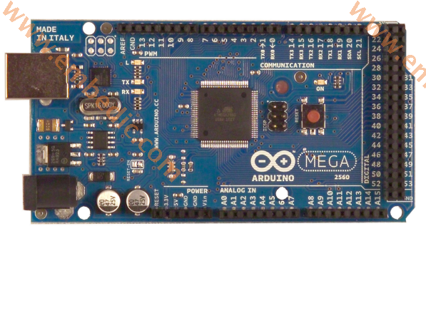
Arduino ATMEGA2560 is the main control development board based on ATMEGA2560. Arduino MEGA2560 is the core circuit board with USB interface. With 54 digital inputs and outputs, it is suitable for designs that require a large number of IO interfaces. The core of the processor is ATMEGA2560, which has 54 digital input/output ports, 16 analog inputs, 4 UART ports, a 16MHz crystal oscillator, a USB port, a power socket, an ICSP header and a reset button. The board has all the resources to support a main control board. Arduino MEGA2560 is also compatible with the expansion board designed for Arduino NUO. Three power supply modes can be automatically selected: the external DC power supply is powered by the power socket; the battery is connected to the GND and VIN pins of the power connector; the USB interface is DC powered.
Working voltage: 5V
Recommended input voltage range: 7-12V
Input voltage range: 6-20V
Digital input and output: 54
Analog input and output ports: 16
Output current of each I/O port: 40mA
Output current of 3.3V pin: 50mA
Memory space: 256KB
SRAM: 8KB
EEPROM: 4KB
Clock frequency: 16MHz
14 digital input and output ports: the working voltage is 5V, and the maximum current that each channel can output and connect is 40mA. Each channel is configured with 20-50K ohm internal pull-up resistors (not connected by default). In addition, some pins have specific functions
4 serial port signals: serial port 0---0(RX) and 1(TX); serial port 1---19(RX) and 18(TX); serial port 2---17(RX) and 16(TX); Serial port 3---15(RX) and 14(TX). The serial port 0 is connected to the internal ATMEGA8U2 USB-to-TTL chip to provide a serial port with TTL voltage level to receive signals.
6 external interrupts: 2 (interrupt 0), 3 (interrupt 1), 18 (interrupt 5), 19 (interrupt 4), 20 (interrupt 3), and 21 (interrupt 2). Trigger interrupt pin, which can be set to trigger on rising edge, falling edge or simultaneously.
14-channel pulse width modulation PWM (0-13): Provide 14-channel 8-bit PWM output.
SPI (53(SS), 51(MOSI), 50(MISO), 52(SCK)): SPI communication interface.
LED (No. 13): Arduino is specially used to test the reserved interface of LED. When the output is high, the LED will be turned on, otherwise the LED will be off when the output is low.
2.16 analog inputs: each channel of ATMEGA2560 Microcontroller has a resolution of 10 bits (that is, the input has 1024 different values), the default input signal range is 0 to 5V, and the upper limit of the input can be adjusted through AREF. In addition, some pins have specific functions
TWI interface (20 (SDA) and 21 (SCL)): support communication interface (compatible with I2C bus).
3. AREF: The reference voltage of the analog input signal.
4. Reset: Reset the single chip microcomputer when the signal is low.
1. Serial port: The built-in 4 UARTs of ATMEGA2560 can communicate with external serial ports; ATMEGA16U2 can access serial port 0 to realize virtual serial ports on USB.
2. TWI (I2C compatible) interface:
3. SPI interface:
Download program
Atmel ATMEGA2560 on the Arduino MEGA2560 has been preset with the bootloader program, so the program can be downloaded directly to the MEGA2560 through the Arduino software.
You can directly download the program to ATmega2560 via the ICSP header on Mega2560.
The firmware of ATmega16U2 can also be upgraded through the DFU tool.
Pay attention to the points
There is a resettable fuse near the USB port on the Arduino Mega ATMEGA2560, which protects the circuit. When the current exceeds 500mA, the USB connection will be disconnected.
Arduino Mega ATMEGA2560 provides an automatic reset design, which can be reset by the host. In this way, the software can be automatically reset through the program to Mega2560 under the Arduino software, without the reset button. This function can be enabled and disabled in the silkscreen "RESET EN" on the printed board.
The design of Arduino Mega ATMEGA2560 is fully compatible with the design of the Arduino USB interface standard version, so the expansion boards used for Arduino UNO and previous series can also be used on Arduino MEGA2560.
Genuino ATMEGA2560 has 256k flash memory to store programs (of which 8kb is used as bootloader), 8kb SRAM and 4kb EEPROM (read and write using EEPROM library)
(1) RAM
Random access memory (English: random access memory, RAM), also known as "random access memory", is an internal memory that directly exchanges data with the CPU, also called main memory (memory). It can be read and written at any time, and is very fast, and is usually used as a temporary data storage medium for operating systems or other running programs. The contents of the storage unit can be taken out or stored at will as needed, and the access speed is independent of the location of the storage unit. This kind of memory will lose its storage content when power is off, so it is mainly used to store short-term use programs. According to the different storage information, random access memory is divided into static random access memory (English: Static RAM, SRAM) and dynamic random access memory (Dynamic RAM, DRAM).
SRAM can save the data stored in it without refreshing the circuit. And DRAM (Dynamic Random Access Memory) needs to be refreshed and charged every once in a while, otherwise the internal data will disappear, so SRAM has higher performance, but SRAM also has its shortcomings, that is, its integration is low, the same The capacity of DRAM memory can be designed into a smaller volume, but SRAM requires a large volume and power consumption. Therefore, SRAM memory on the motherboard takes up a portion of the area. SRAM is fast but expensive. Generally, small-capacity SRAM is used as a cache between a higher-speed CPU and a lower-speed DRAM.
(2) EEPROM
Erasable programmable read-only memory when power is on-a memory chip that does not lose data after power failure. EEPROM can erase existing information on a computer or special equipment and reprogram it. Generally used in plug and play. The erasure of EEPROM does not need to resort to other equipment. It uses electronic signals to modify its content, and uses Byte as the minimum modification unit. It does not need to wash all the data to write, completely getting rid of the EPROM Eraser and programmer. Bondage.
(3) Flash Memory, variants of EEPROM:
In the case of power failure, the stored data information can be divided into NOR type and NAND type flash memory (NAND type is more common, generally speaking NAND type):
The basic storage unit of memory and NOR flash memory is bit, and users can randomly access any bit of information.
The basic storage unit of NAND flash memory is a page. The effective capacity of each page is a multiple of 512 bytes. NAND-type flash memory is erased in block units (erasing block by block). The write operation of the flash memory must be performed in a blank area. If there is data in the target area, it must be erased and then written. Therefore, the erase operation is the basic operation of the flash memory. Generally, each block contains 32 512-byte pages with a capacity of 16KB; when the large-capacity flash memory uses 2KB pages, each block contains 64 pages with a capacity of 128KB.
In short, RAM data cannot be saved when power off, so it is often used as a cache between the CPU and peripherals; EEPROM data is not lost when power off, and is used for programming, reading and writing; sometimes because the amount of data that needs to be rewritten is relatively large, it is Flash Memory (NAND type) appeared on the basis of EEPROM. After we write the program, we download it to the Flash Memory under the bootloader's guidance (because each time the program is downloaded, an area block is refreshed to save the downloaded program, so Flash Memory is used). I believe that novices will have a certain understanding of various memories.
A total of four groups of serial ports. Among them, Serial0 is also connected to the Tmega16U2 USB-to-TTL Serial chip (as described above, we use this serial port to connect the USB to the computer). RX receives data, TX transmits data.
External Interrupts:
2 (interrupt 0),
3 (interrupt 1),
18 (interrupt 5),
19 (interrupt 4),
20 (interrupt 3),
21 (interrupt 2).
Each pin of ATMEGA2560 can be configured as low level trigger, or rising and falling edge trigger. PWM (Pulse Modulation):
2~13 ports;
44~46 mouths.
Provide 8-bit PWM output. Realized by the analogWrite function.
SPI (Serial Peripheral Interface):
50 (MISO), 51 (MOSI), 52 (SCK), 53 (SS). Use the SPI library library to provide convenience. It is for this simple and easy-to-use feature that more and more chips now integrate this communication protocol.
The SPI bus system is a synchronous serial peripheral interface, which enables the MCU to communicate with various peripheral devices in a serial manner to exchange information. Peripheral settings FLASHRAM, network controller, LCD display driver, A/D converter and MCU, etc. The SPI bus system can directly interface with a variety of standard peripheral devices produced by various manufacturers. The interface generally uses 4 lines: serial clock line (SCLK), master input/slave output data line MISO, master output/slave input Data line MOSI and low-level active slave select line CS (some SPI interface chips have an interrupt signal line INT, and some SPI interface chips do not have a host output/slave input data line MOSI).
The communication principle of SPI is very simple. ATMEGA2560 works in a master-slave mode. This mode usually has a master device and one or more slave devices. At least 4 wires are required. In fact, 3 wires can also be used (for one-way transmission, That is half-duplex mode). It is also common to all SPI-based devices, they are SDI (data input), SDO (data output), SCLK (clock), CS (chip select).
Manufacturer: Texas Instruments
IC DGTL MEDIA PROCESSOR 337NFBGA
Product Categories: DSP
Lifecycle:
RoHS:
Manufacturer: Texas Instruments
IC DSP FIXED-POINT 196NFBGA
Product Categories: DSP
Lifecycle:
RoHS:
Manufacturer: Microchip
IC MCU 8BIT 28KB FLASH 44TQFP
Product Categories: 8bit MCU
Lifecycle:
RoHS:
Manufacturer: Microchip
IC MCU 8BIT 32KB FLASH 40DIP
Product Categories: 8bit MCU
Lifecycle:
RoHS:
Looking forward to your comment
Comment
1
2
3
4
5
6
 Popular Searches
8 Bit MCU, Flash, PIC16 Family PIC16F7XX Series Microcontrollers, 20 MHz, 7 KB, 192 Byte, 44 Pi...
EEPROM 2K 256 X 8 2.5V SERIAL EE IND
System-On-Modules - SOM RCM2200
32-bit Arm Cortex-A53 vision processor with ISP, powerful 3D GPU, dual APEX-2 vision accelerat...
IC MCU 8BIT 60KB FLASH 44QFP
DSP 20MHZ 44QFP
Product updates, events, and resources in your inbox


Smart System

Traffic Management

Security

Consumer Electronics

Wireless Technology

Robot

Internet of Things

Industrial Control


