Hello! Welcome to Embedic!
(1) The principle of the breathing lamp, in layman's terms, is to use the change of the duty cycle of the PWM wave to change the effective value of the output voltage to change the brightness of the LED lamp (the brightness of the bulb is determined by the effective value) , And then use the delay to eliminate the flicker effect caused by the duty cycle of the PWM wave. The CCP module of the integrated PIC 16F877A just has this function.
If you want to know more about PIC16F877A Microchip products, please click here.
(2) Briefly introduce the software used.
Programming software: MPLAC X IDE
Simulation software: PRTEUS 8.9
(3) A brief introduction to the registers used.
● T2CON register.
Timer T2 is used in CCP_PWM module to generate PWM period and pulse width.
Set to T2CON=0X04 //Initialize timer T2, set the prescaler to 1:1
● CCP1CON register.
This register is used to set the lower 2 bits of the 10-bit resolution of the PWM wave and to enable the PWM mode.
Set to CCP1CON=0X3C. //Initialize CCP_PWM so that the lower two bits of the 10-bit resolution are 11 and turn on the PWM mode
● PR2 register
This PIC16F877A Microcontroller is used to set the period of the PWM wave.
Set to PR2=99. In this way, the period of the PWM wave obtained in the formula is: 100ns.
● CCPR1L register.
This register is used to change the duty cycle. (So the 10-bit resolution of the initial PWM wave is CCPR1L:CCP1CON<5;4>=0B0000 0000 11)
● Direction register TRISC
This Microchip PIC16F877A is used to set the input/output of the PORTC port.
It can be directly set to TRISC=0X00;
(4) Method 1: Use the source code of the software delay method
#include <xc.h>
void init_pwm();
void delayms(unsigned char x);
void light_control();
unsigned char flag=0;
unsigned int temp=0;
void main(void) {
TRISD=0X00;
PORTD=0X00;
init_pwm();
while(1)
{
light_control();
}
return;
}
void delayms(unsigned char x)
{
unsigned int a,b;
for(a=x;a>0;a--)
for(b=110;b>0;b--);
}
void init_pwm()
{
T2CON=0X04; //Initialize timer T2, set the prescaler to 1:1
CCP1CON=0X3C;//Initialize CCP_PWM so that the lower two bits of the 10-bit resolution are 11, and the PWM mode is turned on
CCPR1L=0X00; //Initialize this register to 0x00, in order to change the duty cycle by changing CCPR1L in the following program to change the effective value of the voltage, and then change the brightness of the LED light
PR2=99;
TRISC=0XFF;
TMR2IF=0;
While(!TMR2IF);
TRISC=0;
}
void light_control()
{
Delayms(1);
If(flag==0)
{
CCPR1L++;
}
Else
{
CCPR1L--;
}
Temp=CCPR1L;
If(temp==0X64)
Flag=1;
If(temp==0X00)
Flag=0;
}
(5) Method 2: Use the source code of the timer delay method.
// PIC16F877A Configuration Bit Settings
//'C' source line config statements
// CONFIG
#pragma config FOSC = XT // Oscillator Selection bits (XT oscillator)
#pragma config WDTE = OFF // Watchdog Timer Enable bit (WDT disabled)
#pragma config PWRTE = ON // Power-up Timer Enable bit (PWRT enabled)
#pragma config BOREN = ON // Brown-out Reset Enable bit (BOR enabled)
#pragma config LVP = OFF // Low-Voltage (Single-Supply) In-Circuit Serial Programming Enable bit (RB3 is digital I/O, HV on MCLR must be used for programming)
#pragma config CPD = OFF / / Data EEPROM Memory Code Protection bit (Data EEPROM code protection off)
#pragma config WRT = OFF // Flash Program Memory Write Enable bits (Write protection off; all program memory may be written to by EECON control)
#pragma config CP = OFF // Flash Program Memory Code Protection bit (Code protection off)
// #pragma config statements should precede project file includes.
// Use project enums instead of #define for ON and OFF.
The above are the configuration bits of MPLAB X IDE, which may be different due to different software.
#include <xc.h>
void init_pwm();
void delayms(unsigned char x);
void light_control();
unsigned char i=0;
unsigned int num=0;
void main(void) {
Init_pwm();
While(1)
{
If(num==5)
{
Light_control();
Num=0;
}
}
Return;
}
void delayms(unsigned char x)
{
Unsigned int a,b;
For(a=x;a>0;a--)
For(b=110;b>0;b--);
}
void init_pwm()
{
ADCON1=0X07;
INTCON=0XE0;
OPTION_REG=0X80;
TMR0=0X06;
T2CON=0X04; //Initialize timer T2, set the prescaler to 1:1
CCP1CON=0X3C; //Initialize CCP_PWM so that the lower two bits of the 10-bit resolution are 11, and the PWM mode is turned on
CCPR1L=0X00; //Initialize this register to 0x00, in order to change the duty cycle by changing CCPR1L in the following program to change the effective value of the voltage, and then change the brightness of the LED light
PR2=99;
TRISC=0XFF;
TMR2IF=0;
While(!TMR2IF);
TMR2IF=0;
TRISC=0;
}
void light_control()
{
...
If(i==0)
CCPR1L++;
If(i==1)
CCPR1L--;
If(CCPR1L==0X63)
//Special attention: When setting the upper limit of CCPR1L, you must calculate the PWM period according to PR2 and then set it. For example: I used PR2=99, and the PWM period is 100ns, all with Enter the pulse width formula to get (CCPR1L:CCP1CON<5:4>)=400=0B0001 1001 00 00.
All CCPR1L=0110 0100=0X64, because the CCP1CON=0X3C is set at the beginning, the lower two bits are 11, so for the convenience of setting, CCPR1L=0x63
(CCPR1L:CCP1CON<5:4>)=0001 1000 11 11=399, the error is not big, it is acceptable.
I=1;SU
If(CCPR1L==0X00)
I=0;
}
void interrupt T0()
{
If(T0IF==1)
{
T0IF=0;
Num++;
}
}
(1) Selection of components
![]()
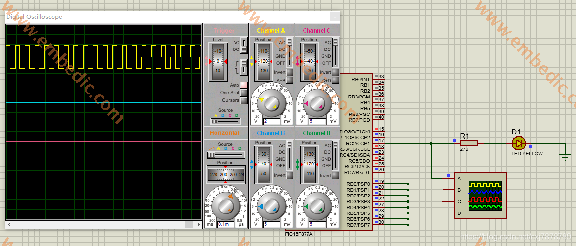
(2) Construction of the circuit
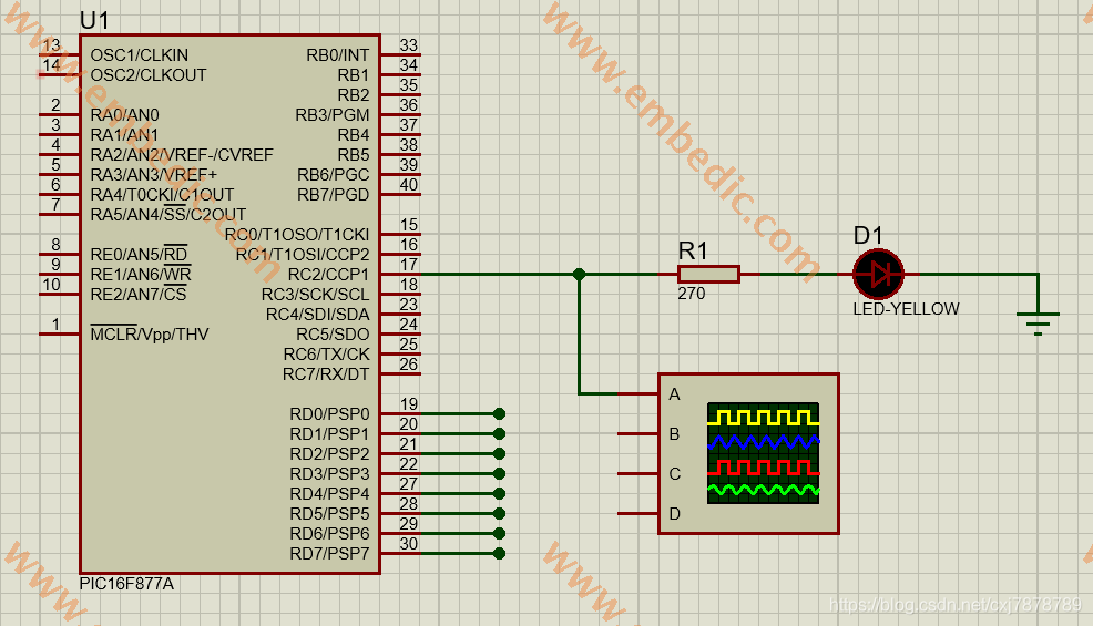
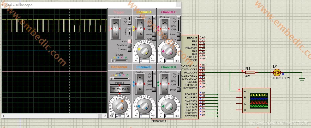
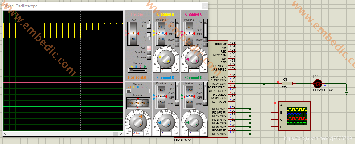
Experimental effect
Manufacturer: Texas Instruments
IC DSP FIXED POINT 737FCBGA
Product Categories: DSP
Lifecycle:
RoHS:
Manufacturer: Texas Instruments
IC DSP FIXED/FLOAT POINT 256BGA
Product Categories: DSP
Lifecycle:
RoHS:
Manufacturer: Texas Instruments
IC DSP FIXED POINT 196NFBGA
Product Categories: DSP
Lifecycle:
RoHS:
Manufacturer: Analog Devices
IC DSP CONTROLLER 32BIT 225BGA
Product Categories: 32bit DSP
Lifecycle:
RoHS:
Looking forward to your comment
Comment
1
2
3
4
5
6
 Popular Searches
8 Bit MCU, Flash, PIC16 Family PIC16F7XX Series Microcontrollers, 20 MHz, 7 KB, 192 Byte, 44 Pi...
EEPROM 2K 256 X 8 2.5V SERIAL EE IND
System-On-Modules - SOM RCM2200
32-bit Arm Cortex-A53 vision processor with ISP, powerful 3D GPU, dual APEX-2 vision accelerat...
IC MCU 8BIT 60KB FLASH 44QFP
DSP 20MHZ 44QFP
Product updates, events, and resources in your inbox


Smart System

Traffic Management

Security

Consumer Electronics

Wireless Technology

Robot

Internet of Things

Industrial Control


