Hello! Welcome to Embedic!
A microcontroller is an integrated circuit chip that includes a CPU, random memory RAM, read-only memory ROM, multiple I/O ports and interrupt system, timer/counter and other functions and is integrated into a silicon chip to form a small but complete microcomputer system. The microcontroller is also known as Microcontroller, or MCU.
Microcontrollers are used in a wide range of applications, from automotive and industrial to home appliances and personal consumer electronics. It can be said that where the control and computing applications, there is a place for microcontrollers.
MSP430 is a 16-bit microcontroller launched by TI, the development of MSP430 now has a number of series of more than 500 models. Different MSP430 series integrated with different peripherals, including Flash, RAM, timer, GPIO, ADC, serial communication module, etc..
MSP430 is known for low power consumption, its low power consumption level in the industry leader, very suitable for battery-powered devices and other areas with high requirements for power consumption.
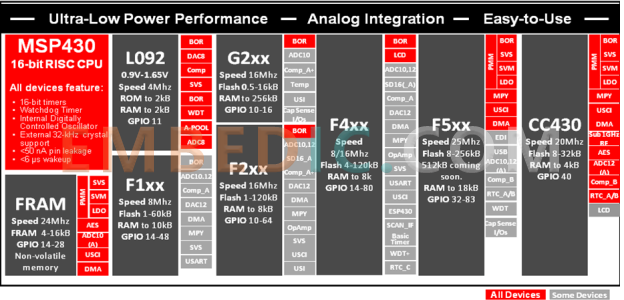
In this tutorial we will use the MSP430FR6989 model, which belongs to the MSP430FR6XX series. This series in the MSP430 product line has a high cost performance, the highest main frequency up to 16MHz, and integrated with a variety of peripherals.
The main features of MSP430FR6989 are as follows.
1. Embedded microcontroller
2. Optimized ultra-low power mode
3. Ultra-low power ferroelectric RAM (FRAM)
4. Intelligent Digital Peripherals
5. High performance analog
6. Multi-function input/output ports
7. Code Security and Encryption
8. Enhanced serial communication
eUSCI_A0 and eUSCI_A1 support:
Universal asynchronous transceiver (UART) with automatic baud rate detection
IrDA encoding and decoding
SPI
eUSCI_B0 and eUSCI_B1 both support:
I2C with multiple slave device addressing support
SPI
Hardware UART and I2C bootloader (BSL)
9. Flexible clocking system
10. Development Tools and Software
Download: MSP430FR6989 Microcontroller specification datasheet pdf
The main resources of the development board are as follows:
1. Development environment configuration
There are 3 commonly used development environments
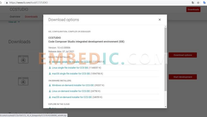
a.CCS(Code Composer Studio)
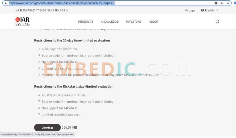
b. IAR (IAR for MSP430)
c. Keil has no official support for MSP430, and the user experience is not good, so this method is not recommended
2. Use of CCS
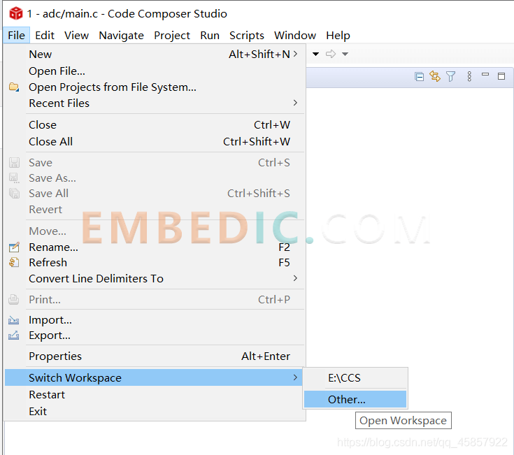
After installing CCS, you first need to set up a workspace space by yourself. It is recommended to create a folder under your disk with a relatively large space margin for storing each workspace, and create a new folder for each workspace under this folder. Folders for later use and organization.
For example, my E:CCS1 here is the workspace with 1 as the space name and built under the CCS folder
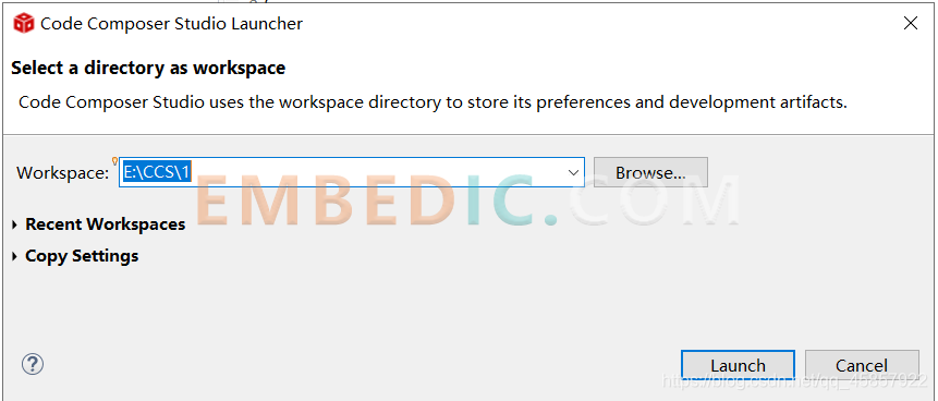
It is also more convenient to switch workspaces
Here is an example of lighting two LED lights that everyone is most familiar with.
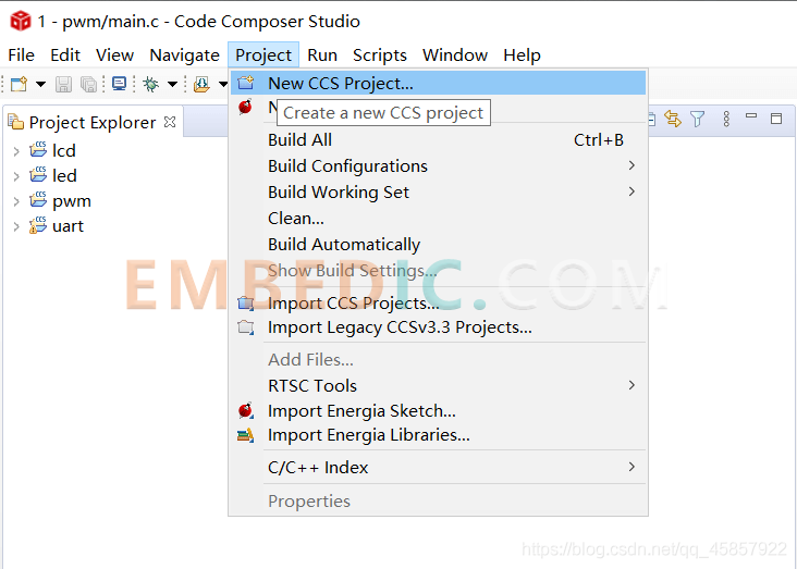
1. New Project
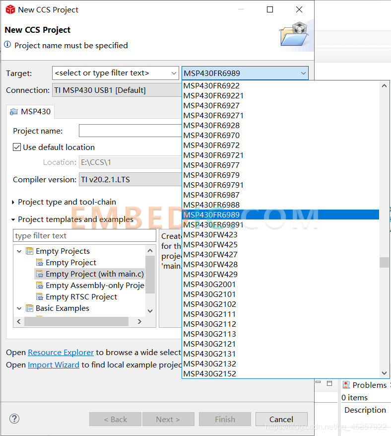
2. Select the chip model
3. Set the project name (take adc as an example here, because there is already a project named led under my workspace)
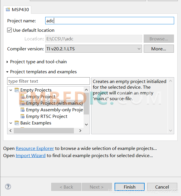
4. Click Finish, and a new project named adc will be created under your workspace.
5. Operation Tips
Here is a way to quickly view the definitions of variables, function bodies, and header files: press the Ctrl key on the keyboard, and at the same time right-click the variable you want to view, you can quickly switch to the included header files. Functions are also available of.
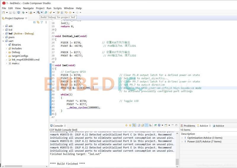
6. Compile the project
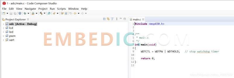
Click the hammer-like button to compile the project. You can see that the project is compiled successfully and the led.out file is generated.
7. Burning project
Connect the download usb cable, the usb interface can not only burn the project, but also send the serial port
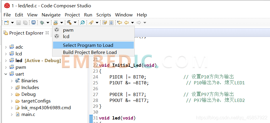
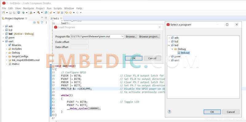
Click the button on the right of the hammer, select Select Program to Load, then click Browse Project, find the led.out generated under the led project, click OK to import, and then wait for the burning process to complete.
The code to light two LED lights is as follows:
#include
/**
* main.c
*/
void Initial_Led(void);
void led(void);
//************************************************** *******************************
//
// Blink the on-board LEDs.
//
//************************************************** *******************************
int main(void)
{
WDTCTL = WDTPW | WDTHOLD; // stop watchdog timer
Initial_Led();
led();
return 0;
}
void Initial_Led(void)
{
P1DIR |= BIT0; // Set the direction of P10 as output
P1OUT &= ~BIT0; // P10 output is 0, turn off LED1
P9DIR |= BIT7; // Set the direction of P97 as output
P9OUT &= ~BIT7; // P97 output is 0, turn off LED2
}
void led(void)
{
// Configure GPIO
P1DIR |= BIT0; // Clear P1.0 output latch for a defined power-on state
P1OUT |= BIT0; // Set P1.0 to output direction
P9DIR |= BIT7; // Clear P9.7 output latch for a defined power-on state
P9OUT |= BIT7; // Set P9.7 to output direction
PM5CTL0 &= ~LOCKLPM5; // Disable the GPIO power-on default high-impedance mode
// to activate previously configured port settings
while(1)
{
P1OUT ^= BIT0; // Toggle LED
P9OUT ^= BIT7;
__delay_cycles(100000);
}
}
Manufacturer: Texas Instruments
IC DGTL MEDIA PROCESSR 1031FCBGA
Product Categories: DSP
Lifecycle:
RoHS:
Manufacturer: Texas Instruments
IC DSP FIXED-POINT 697FCBGA
Product Categories: DSP
Lifecycle:
RoHS:
Manufacturer: Texas Instruments
IC DSP FIX/FLOAT POINT 256BGA
Product Categories: DSP
Lifecycle:
RoHS:
Manufacturer: Texas Instruments
IC DSP FIX/FLOAT POINT 361NFBGA
Product Categories: DSP
Lifecycle:
RoHS:
Looking forward to your comment
Comment
1
2
3
4
5
6
 Popular Searches
8 Bit MCU, Flash, PIC16 Family PIC16F7XX Series Microcontrollers, 20 MHz, 7 KB, 192 Byte, 44 Pi...
EEPROM 2K 256 X 8 2.5V SERIAL EE IND
System-On-Modules - SOM RCM2200
32-bit Arm Cortex-A53 vision processor with ISP, powerful 3D GPU, dual APEX-2 vision accelerat...
IC MCU 8BIT 60KB FLASH 44QFP
DSP 20MHZ 44QFP
Product updates, events, and resources in your inbox


Smart System

Traffic Management

Security

Consumer Electronics

Wireless Technology

Robot

Internet of Things

Industrial Control


