Hello! Welcome to Embedic!
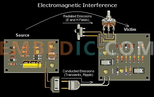
Everyone knows about LEDs, so do you know some knowledge about LED power supply design? For engineers designing LED power supplies, the problem of electromagnetic interference should always be a key issue in the design. In the design process of LED power supplies, Electromagnetic interference EMI is not a small problem, so how to solve this problem?
The article starts with hardware and introduces three major anti-interference measures. Let's move on.
First of all, let's take a look at several factors that can affect EMI/EMC: the circuit structure of the driving power supply; switching frequency, grounding, PCB design, and reset circuit design of the smart LED power supply.
Because the original LED power supply is a linear power supply, but the linear power supply will lose a lot of energy in the form of heat during operation. The working method of the linear power supply makes it necessary to have a voltage device to change from high voltage to low voltage, generally a transformer, and then output DC voltage through rectification.
Although it is bulky and generates a large amount of heat, the advantage is that the external interference is small, the electromagnetic interference is small, and it is easy to solve. Nowadays, more LED switching power supplies are used, all of which are LED driving power supplies in the form of PWM, so that the power transistors work in the on and off states.
When it is turned on, the voltage is low and the current is large; when it is turned off, the voltage is high and the current is small, so the loss generated on the power semiconductor device is also very small. The obvious negative aspect is that electro-magnetic interference (EMI) is likewise much more serious.
The electromagnetic compatibility problem of LED power supply is generally in the power supply of switching circuit. The switching circuit is one of the main sources of interference in the switching power supply. The switch circuit is the core of the LED drive power supply, and the switch circuit is mainly composed of a switch tube and a high-frequency transformer. It produces du/dt pulses with larger amplitudes, wider frequency bands and rich harmonics.
The main reason for this high-frequency pulse interference is: the load of the switch tube is the primary coil of the high-frequency transformer, which is an inductive load. At the moment of turn-on, the primary coil generates a large inrush current, and a high surge peak voltage appears at both ends of the primary coil; at the moment of disconnection, due to the leakage magnetic flux of the primary coil, part of the energy is not transmitted from the primary coil to the secondary coil. In the secondary coil, a damped oscillation with spikes is formed in the circuit, which is superimposed on the turn-off voltage to form a turn-off voltage spike. High-frequency pulses generate more emissions, and periodic signals generate more emissions. In an LED power system, the switching circuit generates a current spike, and when the load current changes, it also generates a current spike.
Basically, in all the problems of electromagnetic interference, it is mainly caused by improper grounding. There are three signal grounding approaches: single-point, multi-point, and also combined. When the switching circuit frequency is lower than 1MHz, the single-point grounding method can be used, but it is not suitable for high frequency; in high-frequency applications, it is best to use multi-point grounding.
Hybrid grounding is a single-point grounding method for low frequencies, and the multi-point grounding is for high frequencies. The layout of the ground wire is the key, and the ground circuits of high-frequency digital circuits and low-level analog circuits cannot be mixed as much as possible. It can be said that proper printed circuit board (PCB) routing is critical to preventing EMI.
In the LED power supply, many smart LED power supplies are controlled by microcontroller, and some LED power supplies use single-chip microcomputers to control the duty cycle of the switching circuit. The watchdog system of the single-chip microcomputer is important in the procedure of the whole LED power supply. It is impossible for all interference sources to be isolated or removed. Once the CPU interferes with the normal operation of the program, the reset system combined with the software processing measures becomes an effective barrier for error correction and defense.
To solve the electromagnetic interference problem of the LED drive power supply, we can start from the following aspects from the hardware:
1. Reduce the interference of the switching power supply itself: Soft switching technology, adding inductance and capacitance elements to the original hard switching circuit, using the resonance of the inductance and capacitance to reduce du/dt and di/dt in the switching process, so that the switching device is turned on When the voltage drops before the current rise, or the current drops before the voltage rise when turned off, to eliminate the overlap of voltage and current.
The changing regularity modulation technology, by regulating the changing frequency fc, distributes the energy focused on fc and also its harmonics 2fc, 3fc ... to the regularity band around them, so as to decrease the EMI amplitude at each regularity point. The selection of components, select components that are not easy to generate noise, and are not easy to conduct and radiate noise. Of certain note is the option of winding parts such as diodes and also transformers. The fast recovery diode with small reverse recovery current and short recovery time is an ideal device for the high frequency rectification part of the switching power supply.
Reasonable use of electromagnetic interference filters, one of the main purposes of EMI filters, grid noise is a kind of electromagnetic interference, which belongs to radio frequency interference (RFI), and also the frequency range of its carried out sound is about 10KHz ~ 30MHz, up to 150MHz. Under normal circumstances, the differential mode interference amplitude is small, the frequency is low, and the interference caused is small; the common mode interference amplitude is large, the frequency is high, and radiation can also be generated through the wire, and the interference caused is relatively large.
To lower performed disturbance, the most reliable method is to install electromagnetic interference filters in the input and outcome circuits of the changing power supply. LED power supplies generally use simple single-stage EMI filters, which mainly include common mode choke coils and filter capacitors. The EMI filter can effectively suppress the electromagnetic interference of the changing power adapter.
2. Minimize the electromagnetic disturbance issue by cutting off the transmission path of the disturbance signal: The first case is that the high-voltage line disturbance can be filtered out with a power line filter. A reasonable and effective switching power supply EMI filter should have a strong inhibitory effect on the differential mode and common mode interference on the power line. Improve the electromagnetic compatibility design of PCB board PCB is the support of circuit components and devices in LED power system, it provides electrical connection between circuit components and devices. With the rapid development of electronic technology, the density of PCB is getting higher and higher.
The quality of PCB design has a great influence on the electromagnetic compatibility of LED power system. Practice has confirmed that even if the circuit schematic design is correct, the improper design of the printed circuit board will adversely affect the reliability of the LED power system. The PCB anti-interference design mainly includes PCB layout, wiring and grounding, and its purpose is to reduce the electromagnetic radiation of the PCB and the crosstalk between the circuits on the PCB.
In addition, the frequency of the humming sound caused by the electromagnetic interference of the general transformer is generally about 50HZ, and the humming sound caused by improper ground wire wiring is about 100HZ due to the frequency doubling of the rectifier circuit, which can be detected carefully. Therefore, when designing the printed circuit board, attention should be paid to adopting the correct method, complying with the general principles of PCB design, and should meet the design requirements of anti-interference.
3. Actively enhance the anti-interference ability of the interfered body: in the LED power supply system, the input/output is also the conduction line of the interference source, and the pickup source for receiving the radio frequency interference signal. We generally take effective measures when designing: use Necessary common mode/differential mode suppression circuit, and also take certain filtering and anti-electromagnetic shielding measures to reduce the interference.
Take various isolation measures (such as photoelectric isolation or magnetoelectric isolation) as far as possible to block the propagation of interference. Lightning protection measures, the LED power system used outdoors or the power lines and signal lines introduced into the room from the outdoor, should consider the lightning protection problem of the system. Typically used lightning defense gadgets are: gas discharge tube, TVS (Short-term Voltage Suppression) and so on.
The gas discharge tube is when the voltage of the power supply is greater than a certain value, usually tens or hundreds of V, the gas breaks down and discharges, and the strong impulse pulse on the power line is guided into the ground. TVS can be seen as two zener diodes connected in parallel and in opposite directions, which conduct when the voltage at both ends is higher than a certain value. Its characteristic is that it can transiently pass currents of hundreds or thousands of A.
Manufacturer: Texas Instruments
IC DGTL MEDIA SOC 337NFBGA
Product Categories: SOC
Lifecycle:
RoHS:
Manufacturer: Texas Instruments
IC DGTL MEDIA SOC 337NFBGA
Product Categories: SOC
Lifecycle:
RoHS:
Manufacturer: Texas Instruments
IC DSP FIX/FLOAT POINT 841FCBGA
Product Categories: DSP
Lifecycle:
RoHS:
Manufacturer: Analog Devices
IC CCD SIGNAL PROCESSOR 88LFCSP
Product Categories: DSP
Lifecycle:
RoHS:
Looking forward to your comment
Comment
1
2
3
4
5
6
 Popular Searches
8 Bit MCU, Flash, PIC16 Family PIC16F7XX Series Microcontrollers, 20 MHz, 7 KB, 192 Byte, 44 Pi...
EEPROM 2K 256 X 8 2.5V SERIAL EE IND
System-On-Modules - SOM RCM2200
32-bit Arm Cortex-A53 vision processor with ISP, powerful 3D GPU, dual APEX-2 vision accelerat...
IC MCU 8BIT 60KB FLASH 44QFP
DSP 20MHZ 44QFP
Product updates, events, and resources in your inbox


Smart System

Traffic Management

Security

Consumer Electronics

Wireless Technology

Robot

Internet of Things

Industrial Control


