Hello! Welcome to Embedic!
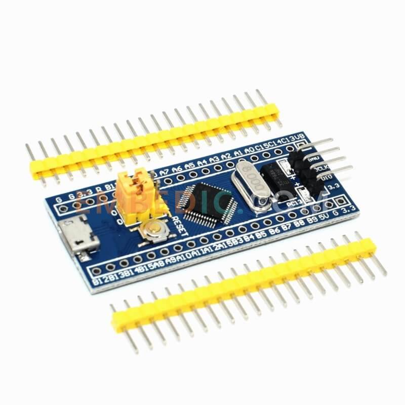
The hardware components of the STM32 minimum system mainly include: power supply circuit, reset circuit, clock circuit, debugging interface circuit, and startup circuit.
Power supply: Generally, 3.3V input is used as the working voltage of the STM32 chip. In practice, many LDOs are used to convert 5V to 3.3V for power supply. In addition, multiple 0.01uf decoupling capacitors are added to the circuit to filter the input voltage and stabilize the input voltage. .
Reset: There are three reset methods in STM32, namely: power-on reset, manual reset, and program automatic reset. Power-on reset refers to the reset of the chip when it is powered on according to the reset circuit built externally; manual reset refers to manual reset through the external reset circuit; program reset refers to the reset of the STM32 chip through code in the software .
The function of the reset circuit of the STM32 single-chip microcomputer is to return the program counter of the single-chip microcomputer to the address 0000H when the reset is performed, so that the program can be re-executed from the beginning.
The reset operation will also reset the values of some registers and storage units to the initial set values, allowing the microcontroller to restart execution.
The difference between the three reset methods of the STM32 microcontroller:
(1) Power-on reset:
Power-on reset needs to be realized through an external capacitor.
.jpg)
In the above circuit, the power-on reset circuit is composed of VCC, C1, and R2.
Assuming that the microcontroller resets when the RESET terminal inputs a high level, then the principle of power-on reset is: at the moment of power-on, the charging current of the C1 capacitor is very large, the capacitor is equivalent to a short circuit, and RESET appears a short-term high level. The microcontroller will be reset. When the voltage across the C1 capacitor reaches VCC, the capacitor C1 is fully charged, which is equivalent to an open circuit, the RESET terminal becomes low level, and the microcontroller starts to run. Thus, automatic power-on reset is realized.
There is a problem that needs attention: in the automatic reset circuit, the high level of the RESET terminal must be maintained for a certain period of time to complete the reset, and this time generally requires about 1ms.
The high level duration is determined by the resistance and capacitance in the power-on reset circuit, and the calculation formula is as follows:
t = 1.1RC (calculation formula of level duration)
In the above figure, the duration of the high level is: t = 1.1*10K*0.1uF = 1.1ms, the required high level reset signal duration is greater than 1ms, and the reset operation can be realized.
(2) Hardware reset:
Hardware reset can still refer to the picture:
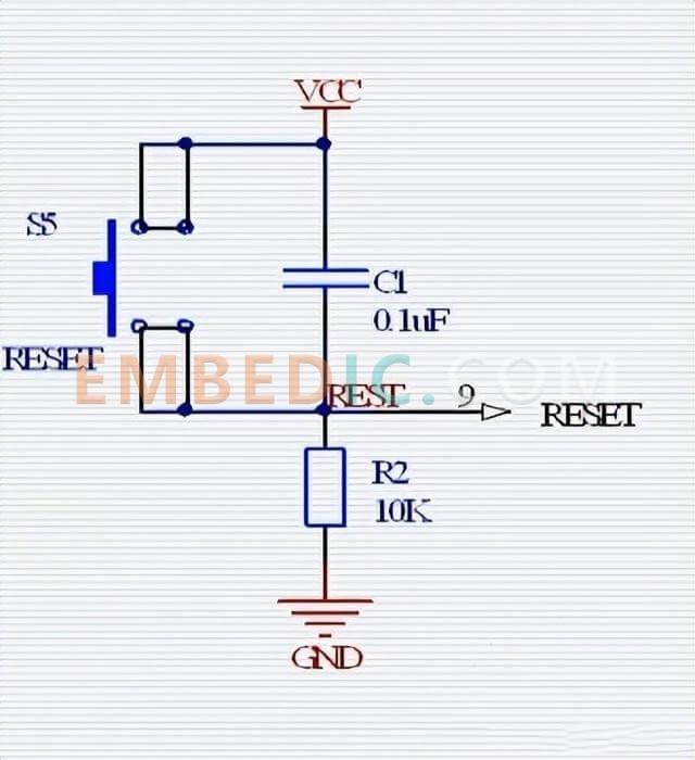
When the button S5 is pressed, the RESET terminal is at a high level, thereby resetting the single-chip microcomputer, and the single-chip microcomputer operates normally when the button S5 is released.
3.1. Clock circuit introduction
A simple clock circuit is as follows:
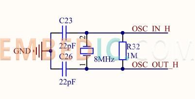
The composition of the clock circuit is : crystal oscillator + start-up capacitor + feedback resistor (MΩ level)
The biggest difference between the two: whether a separate power supply is required.
Passive crystal oscillators do not require power supply, but need an external start-up capacitor; active crystal oscillators need to provide operating voltage.
(1) The role of the capacitance at both ends of the crystal oscillator:
The size of the starting capacitor is generally 10~40pF. Of course, it can be consulted according to different MCU manuals. You could choose 20pF or 30pF if there is no description in the manual. This is an empirical value.
Adjusting the capacitor can fine-tune the oscillation frequency:
In general, increasing the capacitance will decrease the oscillation frequency, while decreasing the capacitance will increase the oscillation frequency;
Feedback resistor: 1M Negative feedback also acts as a current limiter.
The main analysis of the crystal oscillator circuit is as follows:
1. Inside the chip end connected to the crystal oscillator is a linear operational amplifier, which reverses the input by 180 degrees and outputs it. The network composed of load capacitors and resistors at the crystal oscillator provides another 180 degrees of phase shift; the phase shift of the entire loop is 360 degrees, satisfying The phase condition of the oscillation;
2. The function of the resistance connected to the input and output of the crystal oscillator is to generate negative feedback to ensure that the amplifier works in a high-gain linear region, generally at the M ohm level;
3. The function of current limiting prevents the inverter output from overdriving the crystal oscillator and damaging the crystal oscillator. Some crystal oscillators do not need this resistor because the resistor has been integrated into the crystal oscillator.
3.2. Application of clock circuit
STM32 clock tree:
To drive the system clock (SYSCLK), there are three different clock sources to be used:
1) HSI oscillator clock
2) HSE oscillator clock
3) PLL clock
These devices have 2 secondary clock sources as following:
1) 40kHz low-speed internal RC, which can be used to drive an independent watchdog and drive RTC through program selection. RTC is used to automatically wake up the system from shutdown/standby mode.
2) 32.768kHz low-speed external crystal can also be used to drive RTC (RTCCLK) through program selection.
When not in use, either clock source can be independently enabled or disabled, thereby optimizing system power consumption.
3.2.1. 3 internal clocks of STM32
HSI clock: The HSI clock signal is generated by the internal 8MHz RC oscillator, which can be used as the system clock directly or as the PLL input after dividing by 2. The HSI RC oscillator could provide the system clock. The startup time of HSC is shorter than HSE. However, its clock frequency accuracy is poor even after calibration. When the HSI is used as the input of the PLL clock, the maximum frequency that the system clock can get is 64MHz.
LSI Clock: The LSI RC acts as a low-power clock source that can keep running in shutdown and standby modes, clocking the independent watchdog and auto-wake-up units. The LSI clock frequency is between 30-60 khz, is about 40kHz.
PLL clock: The internal PLL can be used to multiply the output clock of the HSI RC or the output clock of the HSE crystal.
3.2.2. Two external clocks
HSE clock: The high-speed external clock signal (HSE) is generated by the following two clock sources:
1) HSE external crystal/ceramic resonator
2) HSE user external clock
To reduce distortion of the clock output and to shorten start-up settling time, the crystal/ceramic resonator and load capacitors must be placed as close as possible to the oscillator pins. The load capacitor value must be adjusted according to the selected oscillator.
LSE Clock: The LSE crystal is a external crystal or ceramic resonator with a 32.768kHz low-speed . It provides a low-power and accurate clock source for a real-time clock or other timing functions.
The boot mode of the STM32 chip can be selected. The mode is selected through the boot mode selection port (BOOT). There are two options: BOOT (B1) and BOOT2 (B2). The boot mode selection method is shown in the figure below:
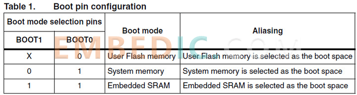
The storage media corresponding to the three startup modes of STM32 are all built-in chips, and they are:
1) Flash memory: Flash built into the chip.
2) SRAM: The built-in RAM area of the chip which is the memory.
3) System memory: a storage inside the chip. When the chip leaves the factory, a section of Bootloader is preset in this area, which is commonly referred to as the ISP program. No one can modify or erase the content of this area after the chip leaves the factory, that is, it is a ROM area, and it uses USART1 as a communication port.
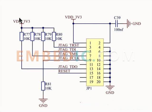
STM32 has two debugging interfaces, JTAG is 5-pin, SWD is 2-wire serial (a total of 4 wires), and the ** circuit has serial ports** and ISP** in addition to the first two.
For example, the commonly used JTAG program**, debugging circuit:
Manufacturer: Analog Devices
IC DSP BLACKFIN 400MHZ 400CSBGA
Product Categories: DSP
Lifecycle:
RoHS:
Manufacturer: Texas Instruments
IC DGTL MEDIA PROCESSR 1031FCBGA
Product Categories: DSP
Lifecycle:
RoHS:
Manufacturer: Texas Instruments
IC DIGITAL MEDIA SOC 338NFBGA
Product Categories: SOC
Lifecycle:
RoHS:
Manufacturer: Texas Instruments
IC DSP FIX/FLOAT POINT 841FCBGA
Product Categories: DSP
Lifecycle:
RoHS:
Looking forward to your comment
Comment
1
2
3
4
5
6
 Popular Searches
8 Bit MCU, Flash, PIC16 Family PIC16F7XX Series Microcontrollers, 20 MHz, 7 KB, 192 Byte, 44 Pi...
EEPROM 2K 256 X 8 2.5V SERIAL EE IND
System-On-Modules - SOM RCM2200
32-bit Arm Cortex-A53 vision processor with ISP, powerful 3D GPU, dual APEX-2 vision accelerat...
IC MCU 8BIT 60KB FLASH 44QFP
DSP 20MHZ 44QFP
Product updates, events, and resources in your inbox


Smart System

Traffic Management

Security

Consumer Electronics

Wireless Technology

Robot

Internet of Things

Industrial Control


