Hello! Welcome to Embedic!
Digital signal processing is different from ordinary scientific calculations and analysis. It emphasizes the real-time nature of arithmetic processing. Therefore, in addition to the high-speed operation and control functions emphasized by ordinary microprocessors, DSP is aimed at real-time digital signal processing. There are many new features in the instruction system and instruction flow, which are as follows:
Hardware multiplier and multi-function arithmetic unit. The hardware multiplier can complete the multiplication operation in a single instruction cycle. This is an important sign that DSP is different from general microprocessor. The multi-function arithmetic unit can complete operations such as addition and subtraction, logic, shift, and data transmission. The new generation DSP even contains multiple parallel computing units to improve its processing capabilities. In view of the characteristics of filtering, correlation, matrix operations and other requirements that require a large number of multiplication and accumulation operations, the multiplier and adder of the arithmetic unit of DSP can complete the two operations of multiplication and accumulation within one clock cycle. In recent years, some DSPs such as ADSP2106X and DSP96000 series DSPs can perform multiplication, addition, and subtraction operations at the same time, which greatly speeds up the butterfly operation of FFT.
 Bus structure
The traditional general-purpose processor uses a unified program and data space, a shared program and data bus structure, the so-called Feng. Neumann structure. DSP generally adopts the Harvard structure in which the data bus and the program bus are separated or the improved Harvard structure, which greatly improves the instruction execution speed. Multiple sets of buses on the chip can perform instruction fetching and multiple data access operations at the same time. Many DSP chips are embedded with DMA controllers. With the on-chip multi-bus structure, the data block transmission speed is greatly improved.
DSP is oriented to data-intensive applications. With frequent data access, the calculation of data addresses also takes a lot of time. A dedicated addressing unit is configured inside the DSP for address modification and update. They can automatically modify the content before or after the addressing access to point to the next address to be accessed. The address modification and update work in parallel with the arithmetic unit, and no additional time is required. The address generator of the DSP supports direct addressing and indirect addressing operations. Most DSPs also support bit-reversed addressing (used for FFT algorithms) and circular addressing (used for digital filtering algorithms).
In response to the need for data-intensive calculations in digital signal processing, DSPs have high requirements for program and data access time. In order to reduce the transmission time of instructions and data, many DSPs integrate high-speed program memory and data memory to improve programs and data. The speed of access to memory.
DSP mostly uses pipeline technology, that is, the execution process of an instruction is divided into several stages, such as instruction fetching, decoding, fetching, and execution, and each stage is called a first-level pipeline. Each instruction is performed by multiple functional units on the chip respectively to fetch instructions, decode, fetch numbers, and execute operations, thereby reducing the execution time of each instruction without increasing the clock frequency.
DSP hardware design includes: hardware scheme design, DSP and peripheral device selection, schematic design, PCB design and simulation, hardware debugging, etc. In the previous lecture, we described in detail the two parts of hardware scheme design, DSP and peripheral device selection, this lecture described in detail the schematic design, PCB design, hardware debugging and so on. In order to share design experience, and to improve everyone's design efficiency.
1, system resource planning
The prerequisite of hardware design is to plan the resources of the entire system, and finally get the system's resource allocation table, namely MemoryMap. Table 1 provides an address mapping table of an image processing system designed with TMS320DM642.
Through Table 1, we can clearly see the address of the program space, data space, image input port and other resources. After planning the system resources, our hardware design can have an overall plan, otherwise the designed schematic diagram is very blind "passive water".
2, hardware schematic design
DSP chip manufacturers generally provide the corresponding EVM (evaluation board) reference schematic design when designing each DSP chip. You can download it for free through the Internet or buy the original EVM board. We will not explain the principle of a certain board in detail. Based on the author's years of experience in DSP design, we will summarize the design skills and share with you.
(1) Clock circuit. The DSP clock can be provided externally or by the crystal oscillator on the board. However, external clock input is often used in general DSP systems, because when an external clock is used, the clock has high precision, good stability and easy use. Because DSP work is based on the clock, if the clock quality is not high, the reliability and stability of the system are difficult to guarantee. Therefore, if an external clock is used, the stability and burr of the crystal oscillator should be comprehensively tested when selecting the crystal oscillator so that the DSP system can work reliably.
(2) Reset circuit. The power-on reset circuit and the manual reset circuit should be designed at the same time, which can be easily reset manually when a fault occurs in the system operation. For the reset circuit, on the one hand, it should ensure that the reset low level time is long enough (generally more than 20ms) to ensure reliable reset of the DSP; on the other hand, it should ensure good stability to prevent the DSP from resetting by mistake.
(3) In the DSP circuit, all input signals must be clearly processed, and cannot be suspended or ignored. In particular, it should be noted that if the non-maskable hardware interrupt NMI is not used in the design, the hardware design should ensure that its corresponding pin is pulled high, otherwise unpredictable results will occur when the program is running; if the NMI is used in the design, The corresponding pin should also be set to high level during the normal execution of the program.
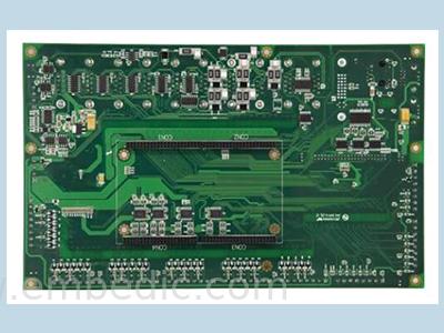
3, high frequency PCB design
Digital devices are moving in the direction of high speed, low power consumption, small size, and high anti-interference. This development trend puts forward many new requirements for the design of printed circuit boards. Based on years of experience in hardware design work, the author summarizes some high-frequency wiring techniques for your reference.
(1) High-frequency circuits tend to have high integration and high wiring density. The use of multilayer boards is not only necessary for wiring, but also an effective means to reduce interference.
(2) The less the lead bends between the pins of high-speed circuit devices, the better. It is best to use a full straight line for the wiring of the high-frequency circuit, and it needs to be turned. It can be turned by a 45° broken line or a circular arc. Meeting this requirement can reduce the external emission and mutual coupling of high-frequency signals.
(3) The shorter the lead between the pins of the high-frequency circuit device, the better.
(4) Alternation of lead layers between pins of high-frequency circuit devices is as small as possible. The so-called "the less the inter-layer alternation of the leads, the better" means that the fewer vias (Via) used in the component connection process, the better. According to measurements, one via can bring about 0.5pF of distributed capacitance and reduce the number of vias. Can significantly increase speed.
(5) High-frequency circuit wiring should pay attention to the "cross interference" introduced by the close parallel routing of signal lines. If parallel distribution cannot be avoided, a large area of "ground" can be arranged on the opposite side of parallel signal lines to greatly reduce interference. Parallel routing in the same layer is almost unavoidable, but in two adjacent layers, the routing directions must be taken perpendicular to each other.
(6) Implement ground wire enclosing measures for particularly important signal lines or local units, that is, draw the outer contour line of the selected object. Using this function, it is possible to automatically perform the so-called "package ground" processing on the selected important signal lines. Of course, using this function for partial package processing of clocks and other units will also be very beneficial to high-speed systems.
(7) Various signal traces cannot form a loop, and the ground wire cannot form a current loop.
(8) A high-frequency decoupling capacitor should be installed near each integrated circuit block.
(9) When connecting analog ground wire, digital ground wire, etc. to public ground wire, use high frequency choke link. In the actual assembly of the high-frequency choke link, the high-frequency ferrite bead with a wire through the center hole is often used. It is generally not expressed in the circuit schematic diagram, and the resulting netlist (netlist) is not Including this type of component, it will ignore its existence when wiring. In view of this reality, you can use it as an inductor in the schematic, define a component package separately for it in the PCB component library, and manually move it to a suitable position near the common ground line before wiring.
(10) The analog circuit and the digital circuit should be arranged separately, and the power and ground should be connected at a single point after independent wiring to avoid mutual interference.
(11) Before DSP, off-chip program memory and data memory are connected to the power supply, filter capacitors should be added and placed as close as possible to the power supply pins of the chip to filter out power supply noise. In addition, shielding is recommended around key parts such as DSP and off-chip program memory and data memory to reduce external interference.
(12) The off-chip program memory and data memory should be placed as close as possible to the DSP chip, and at the same time, the layout should be reasonable so that the length of the data line and the address line are basically the same. Especially when there are multiple memories in the system, the clock line to each memory should be considered. The clock input distance is equal or a separate programmable clock driver chip can be added. For a DSP system, an external memory with an access speed similar to that of the DSP should be selected, otherwise the high-speed processing capability of the DSP will not be fully utilized. The DSP instruction cycle is in the order of nanoseconds, so the most likely problem in DSP hardware systems is high-frequency interference. Therefore, when making printed circuit boards (PCBs) for DSP hardware systems, special attention should be paid to address lines and data lines. The wiring of the signal line must be correct and reasonable. When wiring, try to make high-frequency lines short and thick, and keep them away from signal lines that are susceptible to interference, such as analog signal lines. When the circuit around the DSP is complex, it is recommended to make the DSP and its clock circuit, reset circuit, off-chip program memory, and data memory into the smallest system to reduce interference.
(13) When following the above principles and proficient in the use of design tools, after manual wiring is completed, high-frequency circuits generally need to be simulated with advanced PCB simulation software in order to improve the reliability and productivity of the system
Manufacturer: Microchip
IC MCU 8BIT 28KB FLASH 28QFN
Product Categories: 8bit MCU
Lifecycle:
RoHS:
Manufacturer: Analog Devices
IC DSP CTRLR 24B W/CODEC 289BGA
Product Categories: DSP
Lifecycle:
RoHS:
Manufacturer: Texas Instruments
IC FIXED POINT DSP 196NFBGA
Product Categories: DSP
Lifecycle:
RoHS:
Looking forward to your comment
Comment
1
2
3
4
5
6
 Popular Searches
8 Bit MCU, Flash, PIC16 Family PIC16F7XX Series Microcontrollers, 20 MHz, 7 KB, 192 Byte, 44 Pi...
EEPROM 2K 256 X 8 2.5V SERIAL EE IND
System-On-Modules - SOM RCM2200
32-bit Arm Cortex-A53 vision processor with ISP, powerful 3D GPU, dual APEX-2 vision accelerat...
IC MCU 8BIT 60KB FLASH 44QFP
DSP 20MHZ 44QFP
Product updates, events, and resources in your inbox


Smart System

Traffic Management

Security

Consumer Electronics

Wireless Technology

Robot

Internet of Things

Industrial Control


