Hello! Welcome to Embedic!
In real production life, such as product counting, speed measurement, time control and other occasions, often need to use the timer and counter function. 8051 microcontroller has two built-in timer and counter, can be used to achieve the timing and counting function, let us learn together in the 51 microcontroller timer and counter it!
1. 51 microcontroller has two sets of timers/counters, because both timing and counting, so called timers/counters.
2. Timer/counter and microcontroller CPU are independent of each other. The working process of timer/counter is done automatically and does not need CPU's participation.
3. The timer/counter in 51 microcontroller is to add 1 to the data in the register according to the internal clock of the machine or the external pulse signal.
4. With timer/counter, the efficiency of microcontroller can be increased, and some simple work of repeatedly adding 1 can be left to timer/counter. And the timer can also realize the role of precise timing. Let the CPU handle some other complicated things.
5. (CPU timing related).
Example.
When the external crystal is 12MHz, the specific value of the relevant cycle of the 51 microcontroller is
Oscillation cycle = 1/12us; state cycle = 1/6us; machine cycle = 1us; instruction cycle = 1~4us;
In fact, the timer and counter in microcontroller are actually the same physical electronic components. Only the counter records what happens outside the microcontroller (accepting external pulses), while the timer is a very stable counter provided by the microcontroller itself, the stable counter is the crystal parts connected to the microcontroller, this point we need to distinguish with the timer to avoid confusion.
About 8051 series microcontroller has two timers: T0 and T1, respectively, called timer and timer T1, these two timers are 16-bit timer / counter; 8052 series microcontroller added a third timer / counter T2; they all have timing or event counting function, commonly used in time control, time delay, external time counting and detection occasions.
The counter is used to count the number of negative jumps in the pulse input from T0 (P3.4) and T1 (P3.5) pins. Negative jumper means that the previous machine cycle is sampled high, and the next machine cycle is low. The high and low levels of the input pulses should be held for at least one machine cycle to ensure correct sampling, so the maximum frequency of the input pulses is half of the internal pulse frequency of the microcontroller. If the internal pulse frequency is 1 MHz, the maximum count frequency is 0.5 MHz.
The timing function is implemented by the microcontroller by counting the internal machine pulse signal, and the count value multiplied by the machine cycle is the corresponding time. For example, if the microcontroller uses a 12 MHz crystal, the internal pulse frequency of the machine is 1 MHz and the machine cycle is 1 pμs), if the total count is 1000 times, the time taken is 1 ms.
Each timer/counter is 16 bits and consists of two 8-bit dedicated registers respectively. The low 8 bits are recorded as TL and the high 8 bits are recorded as TH, which are used to store the low 8 bits and high 8 bits of the initial value of 16-bit count.
In order to control the normal operation of the timer, there are also two 8-bit special registers TMOD and TCON, TMOD is used to control the working mode of the timer/counter, TCON is used to control the start and stop of TO and T1, as well as to save the overflow and interrupt flags of TO and T1, the contents of TMOD and TCON are set by programming, both of them are automatically cleared when the system is reset. .
In modes 0, 1 and 2, the operating modes of T0 and T1 are the same; in mode 3, the operating modes of the two timers/counters are different.
A 13-bit timer/counter is formed by the low 5 bits of TL0 and all 8 bits of TH0; after the timer/counter is started, the number of timing or counting pulses is added to TL0, starting from the pre-set initial value (time constant) and incrementing by 1.
When TL0 is full, it will feed TH0 until the 13-bit register is full and overflowed; when it is overflowed, the timer/counter hardware will automatically clear the 13-bit register value to 0 and set the interrupt mark TF0 to 1; if further timing/counting is needed, the time constant needs to be reset using the relevant instruction and the interrupt mark TF0 of the timer/counter needs to be set to 0.
Mode 1 is almost identical to mode 0. The only difference is that the registers TH0 and TL0 in mode 1 together constitute a 16-bit timer/counter to participate in the operation, so the timing range is larger than that in mode 0.
This mode is also called auto-reload preset number mode; when the value of timer register TH0/TL0 overflows, the timer/counter hardware device will automatically clear the value of register TH0/TL0 by 0 to restart the operation.
But sometimes, our timing/counting operation needs to be repeated several times, if nothing is done when it overflows, then it will start timing/counting from 0 in the second round of timing, which is not what we want.
So, to ensure that after each overflow, the operation of restarting timing is what we want, then we have to reload the preset (time constant) into some place; and the operation of reloading the preset is done automatically by the hardware device, no human intervention is needed, so this working mode is called automatic reloading preset mode; since the preset needs to be reloaded, then the preset must be stored in some to ensure a successful reloading operation.
In working mode 2, the automatic reload preset number is stored in the high 8 bits of the timer/counter register, that is, in TH0, and only TL0 is left to participate in the timing/counting operation; obviously, the timing/counting orientation is much smaller.
Note: This working mode is often used in baud rate generator (serial communication), T1 works in serial mode 2; when used in this way, the timer is to provide a time reference; after the count overflow, there is no need to do too much, only one thing can be done, which is to reload the preset number and start counting again, and there is no need for any delay in between.
Since timer/counter T1 has no working mode 3, if timer T0 is set to working mode 3, then TL0 and TH0 will be split into two independent 8-bit timers.
To use 8051 microcontroller to control 8 LEDs to notify the flashing of 1S cycle, design the circuit schematic and write the program.
Circuit schematic diagram is as follows.
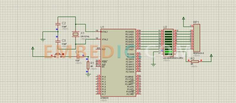
Figure 5-2 circuit schematic diagram
The program is as follows.
#includeint main(void){ unsigned char counter; //Set unsigned character type variable to store the number of timer interrupts TMOD = 0x0a; //Set T0 to timer mode, controlled by TR0 start and stop, operating mode 1 TH0 = (65536-46083)/256; // Initialize the high 8 bits of T0 TL0=(65536-46083)%256; //Initialize the low 8 bits of T0 TF0=0; //Initialize the timer overflow flag P0=0xff; //Turn off the LED counter=0; //Start counting from 0 TR0=1; //Start timer 0 while(1) { while(TF0==1) { counter++; //if timer overflow if(counter==20)//even if time reaches 1S { P0=~P0;//reverse LED state to make LED blink counter=0;//start counting from 0 again } //reinitialize T0 TH0=(65536-46083)/256; TL0=( 65536-46083)%256; TF0=0; } }
In the hardware circuit Figure 5-2, a crystal of 11.059 2 MHz is used, and the crystal circuit and reset circuit in the figure are in common form. 8 light-emitting diode LEDs are connected to the 8 bits of the PO port in the form of common anode.
Which R1-R8 for the current limiting resistor, to prevent excessive current burn LED and microcontroller port, the value of the available voltage and drive LED light required to approximate the ratio of current selected, the current for this example is 5 V/470 ~ 11 mA, LED light can be guaranteed.
As the crystal pulse frequency of 11.059 2 MHz, each machine cycle for 12 pulse frequency, the machine cycle T = 1/ f = 12/11.059 2 = 1.085 us. If the work mode 0, and set the initial value of 0. The longest timing time of 8192 × 1.085 ~ 9 ms, and the question requires the blinking cycle up to 1 s, available software counting method The method of software counting is available.
Timing 8 ms per overflow, the detection of 125 overflows can be obtained 1 s timing time; using work mode 1 can obtain the longest timing time of 65536 × 1.085 ~ 7l ms, if each timing 50 ms, then 20 overflows can be obtained 1 s timing time, because each overflow requires a series of operations to bring timing errors, so the use of work mode 1 overflow fewer times The timing is more accurate.
Timing 50 ms need to count 50 000 / 1.085 = 46083 machine cycles, in mode 1 timer need to set the initial value of 65536-46 083 = 19453, converted to hexadecimal 0x4bfd, binary to set the initial value of the timer, at this time the low 8 bits set to TLO = (65 536-46 083) %256, the high 8 bits set to TH0 = ( 65 536-46083)/256, can ensure that the timing 50 ms after the overflow, overflow flag TFO automatically set to 1, and apply for interrupt.

Manufacturer: Texas Instruments
IC DSP FIX/FLOAT POINT 841FCBGA
Product Categories: DSP
Lifecycle:
RoHS:
Manufacturer: Analog Devices
IC DSP 12BIT 300MHZ 120LQFP
Product Categories: DSP
Lifecycle:
RoHS:
Manufacturer: Microchip
IC MCU 8BIT 28KB FLASH 64QFN
Product Categories: 8bit MCU
Lifecycle:
RoHS:
Manufacturer: Texas Instruments
IC DSP FIXED/FLOAT POINT 256BGA
Product Categories: DSP
Lifecycle:
RoHS:
Looking forward to your comment
Comment
1
2
3
4
5
6
 Popular Searches
8 Bit MCU, Flash, PIC16 Family PIC16F7XX Series Microcontrollers, 20 MHz, 7 KB, 192 Byte, 44 Pi...
EEPROM 2K 256 X 8 2.5V SERIAL EE IND
System-On-Modules - SOM RCM2200
32-bit Arm Cortex-A53 vision processor with ISP, powerful 3D GPU, dual APEX-2 vision accelerat...
IC MCU 8BIT 60KB FLASH 44QFP
DSP 20MHZ 44QFP
Product updates, events, and resources in your inbox


Smart System

Traffic Management

Security

Consumer Electronics

Wireless Technology

Robot

Internet of Things

Industrial Control


