Hello! Welcome to Embedic!
The debate between Programmable Logic Controllers (PLCs) and microcontrollers is a pivotal one in the field of industrial automation and control systems.
In this article, we will delve into the distinctions between PLCs and microcontrollers, providing insights that will help you navigate their features, applications, and advantages, ultimately aiding you in choosing the most suitable technology for your specific automation requirements.
Programmable logic controller (PLC for short), a digital electronic device with microprocessor, digital logic controller for automation control, control instructions can be loaded at any time in the memory storage and execution.
Programmable logic controller consists of an internal CPU, instruction and data memory, input and output units, power supply modules, digital and analog units modular combination of PLC can receive (input) and send (output) a variety of types of electrical or electronic signals, and use them to control or supervise almost all kinds of mechanical and electrical systems.
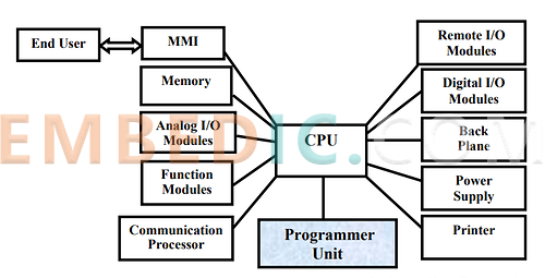
Generally speaking, PLC is divided into two types: box type and module type. But their composition is the same, for the box type PLC, there is a CPU board, I / O board, display panel, memory block, power supply, etc., of course, according to the performance of the CPU is divided into a number of models, and according to the number of I / O points and a number of specifications. For modular PLCs, there are CPU modules, I/O modules, memory, power supply modules, and baseboards or racks. Regardless of the type of structure of the PLC, it belongs to the bus type open structure, and its I/O capacity can be expanded and combined according to the user's needs. the basic structure of the PLC block diagram is as follows:
Power supply module
The power supply in some PLCs, which is combined with the CPU module, and some are separate, is mainly used to provide working power for the integrated circuits of each PLC module. At the same time, some also provide 24V operating power for the input circuits. The power supply is usually 220VAC or 110VAC if it is an AC power supply, and 24V if it is a DC power supply.
Central Processing Unit
The CPU in the PLC is the core of the PLC, which receives and stores the user program and data according to the function given by the system program of the PLC, collects the state or data sent by the field input device by scanning, and stores them in the planning cache, and at the same time, diagnoses the working state of the power supply and the internal circuitry of the PLC, and the grammatical errors in the programming process. Into operation, from the user program memory to read instructions one by one, after analyzing and then according to the tasks set out in the instructions to produce the appropriate control signals to command the relevant control circuits, as with personal computers, mainly by the operator, controllers, registers and the realization of the link between them, data, control and status buses, and peripheral chips, bus interfaces and related circuits. It determines the scale of the control performed, the operating speed, the memory capacity and so on.
Memory
Memory is mainly used to store programs and data, and is an indispensable component of the PLC, which stores program instructions and data written and edited inside the PLC, and can usually be expanded by using special memory cards such as RAM or EEPROM, but the expansion capacity varies depending on the brand and model.
Input/Output Unit
PLC's external functions, mainly through a variety of input / output modules and the outside world, according to the number of I / O points to determine the module specifications and the number of I / O modules can be more or less, but the maximum number of CPU can manage the basic configuration of the ability to be limited by the maximum number of slots on the baseboard or rack. I / O module integrated PLC I / O circuit, its input buffer to reflect the state of the input signal, the output point to reflect the state of the output latch. reflect the output latch status.
The input unit is used to link the signaling actions of the captured input components and send the data to memory via an internal bus for processing by the CPU as part of the driver instructions.PLC Input ModulesThe architecture of the PLC system and the selection of the input module product depends on the level of the input signals that need to be monitored.
Variable signals from different types of sensors to be monitored and process control can cover the input signal range from ±10mV to ±10V.
Output unit is used to drive the interface of external loads, the main principle is processed by the CPU to write in the PLC program instructions, judgment to drive the output unit in order to control the external loads, such as indicators, electromagnetic contactors, relays, gas (oil) valves and so on.
PLC output modules are used in industrial environments to control brakes, air valves and motors etc. The analog output range of the PLC system includes ±5V, ±10V, 0V to 5V, 0V to 10V, 4 to 20mA, or 0 to 20mA.
Although the ladder program used by the PLC often uses many relays, timers and counters and other names, but the PLC does not physically have these hardware internally, but rather the memory and programmed to do the logic control editing, and through the output components connected to the external mechanical devices to do the physical control. Therefore, the hardware space required for the controller can be greatly reduced. In fact, the PLC executes the ladder program in a way that the program code is first read into the CPU line by line in a scanning manner and then finally executes the control operation. The whole scanning process includes three major steps, "Input Status Check", "Program Execution", and "Output Status Update", which are described as follows:
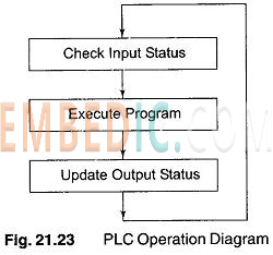
Step 1 "Input status check":
The PLC first checks the status of the switches or sensors connected to the inputs (1 or 0 for on or off) and writes their statuses to the corresponding locations Xn in the memory.
Step 2 "Program Execution":
The ladder program is loaded into the CPU line by line for operation. If the input of contact status is required for program execution, the CPU will query and retrieve it directly from the memory. The result of the output coil operation is stored in the corresponding position in the memory and is not reacted to the output terminal Yn for the time being.
Step 3 "Output state update":
Update the output status in step 2 to the PLC output contact and go back to step 1 again.
These three steps are called the PLC scanning cycle, and the time required for completion is called the PLC response time. If the PLC input signal time is less than this response time, there is a possibility of misinterpretation. After each program execution and before the next program execution, the output and input states will be updated once, so this operation is called "end-of-program regeneration" for the outputs and inputs.
A microcontroller is a compact integrated circuit (IC) that contains a processor (CPU), memory, and input/output peripherals. It is designed to execute specific tasks or control various devices within a system. Microcontrollers are commonly used in embedded systems, which are systems that have dedicated functions and are embedded within larger devices or products.

Microcontrollers function as integral components within systems to manage specific tasks or functions in devices. They operate through a series of steps involving data interpretation, processing, memory storage, and interaction with input/output (I/O) peripherals. Here's a breakdown of how microcontrollers work:
Data Interpretation:
Central Processor:
Data Memory:
Program Memory:
Data Processing:
Action and I/O Interaction:
Communication and Collaboration:
Feedback Loop:
|
Aspect |
PLC |
Microcontroller |
|
Scope and Complexity |
Complex automation tasks in industry |
Wide range of applications, from simple to complex |
|
I/O Handling |
Many I/O ports for industrial devices |
Limited I/O pins for simpler tasks |
|
Reliability |
High, with redundancy and fault tolerance |
Moderate, depending on the model and usage |
|
Environment |
Rugged for industrial environments |
Versatile, not necessarily ruggedized |
|
Scalability |
Easily expandable for larger systems |
Limited scalability |
|
Programming Languages |
Specialized languages (e.g., ladder logic) |
Various languages, including C/C++, Assembly |
|
Software Ecosystem |
Industrial-focused software platforms |
Wide range of development tools and libraries |
|
Safety Features |
Built-in safety features and fail-safes |
Fewer built-in safety features |
|
Size and Cost |
Larger size and higher cost |
Smaller size and often lower cost |
|
Development Flexibility |
Limited hardware and software flexibility |
High flexibility for customization |
|
Development Time |
Longer setup time due to complexity |
Generally quicker setup and programming |
When deciding whether to use a PLC or a microcontroller for a project, consider the following factors:
#1 Complexity of the Task: Choose a PLC for complex automation tasks with numerous inputs, outputs, and control requirements. Opt for a microcontroller for simpler tasks or projects with specific customization needs.
#2 Industrial vs. Non-Industrial Setting: If the application is in an industrial environment with rugged conditions and high reliability requirements, a PLC might be more suitable. For non-industrial settings, a microcontroller could be sufficient.
#3 Scalability: If the project might expand in the future, a PLC's scalability can be advantageous. Microcontrollers are better suited for smaller-scale applications.
#4 Budget and Size Constraints: Microcontrollers are often more cost-effective and compact, which can be crucial for projects with tight budgets or limited space.
#5 Programming Knowledge: Consider the programming languages and tools available for each option. If your team is more familiar with a certain language, it might influence your choice.
#6 Safety Requirements: If safety is a critical concern, PLCs are designed with built-in safety features that might be advantageous.
#7 Development Time: Microcontrollers can be quicker to set up and program, making them preferable for rapid prototyping and development.
Conclusion
In conclusion, the choice between a PLC and a microcontroller hinges on the specific demands of your automation project, considering factors such as complexity, scalability, customization, and control requirements.
Whether you are designing a factory automation system, developing a smart home setup, or creating a specialized control application, the choice between a PLC and a microcontroller will undoubtedly shape the efficiency, adaptability, and success of your automation endeavors.

Manufacturer: Texas Instruments
IC DGTL MEDIA PROCESSR 1031FCBGA
Product Categories: DSP
Lifecycle:
RoHS:
Manufacturer: Silicon Labs
IC MCU 8BIT 8KB FLASH 10DFN
Product Categories: 8bit MCU
Lifecycle:
RoHS:
Manufacturer: Texas Instruments
IC DSP FIX/FLOAT POINT 841FCBGA
Product Categories: DSP
Lifecycle:
RoHS:
Manufacturer: Microchip
IC MCU 8BIT 32KB FLASH 28SOIC
Product Categories: 8bit MCU
Lifecycle:
RoHS:
Looking forward to your comment
Comment
1
2
3
4
5
6
 Popular Searches
8 Bit MCU, Flash, PIC16 Family PIC16F7XX Series Microcontrollers, 20 MHz, 7 KB, 192 Byte, 44 Pi...
EEPROM 2K 256 X 8 2.5V SERIAL EE IND
System-On-Modules - SOM RCM2200
32-bit Arm Cortex-A53 vision processor with ISP, powerful 3D GPU, dual APEX-2 vision accelerat...
IC MCU 8BIT 60KB FLASH 44QFP
DSP 20MHZ 44QFP
Product updates, events, and resources in your inbox


Smart System

Traffic Management

Security

Consumer Electronics

Wireless Technology

Robot

Internet of Things

Industrial Control


