Hello! Welcome to Embedic!
The Breadboard LED Watch is an innovative electronics and DIY project for hobbyists. The watch is based on an ATtiny84A microcontroller and some electronic components designed to display the time in hours and minutes on a bubble 7-segment LED display. For a nice look you can use a fancy case with dimensions of about 37x23x3.5 mm.
In this article, we will provide a comprehensive technical guide on how to build a breadboard LED watch using an ATtiny84A microcontroller.
Required Components:
To build a breadboard LED watch, you will need the following:
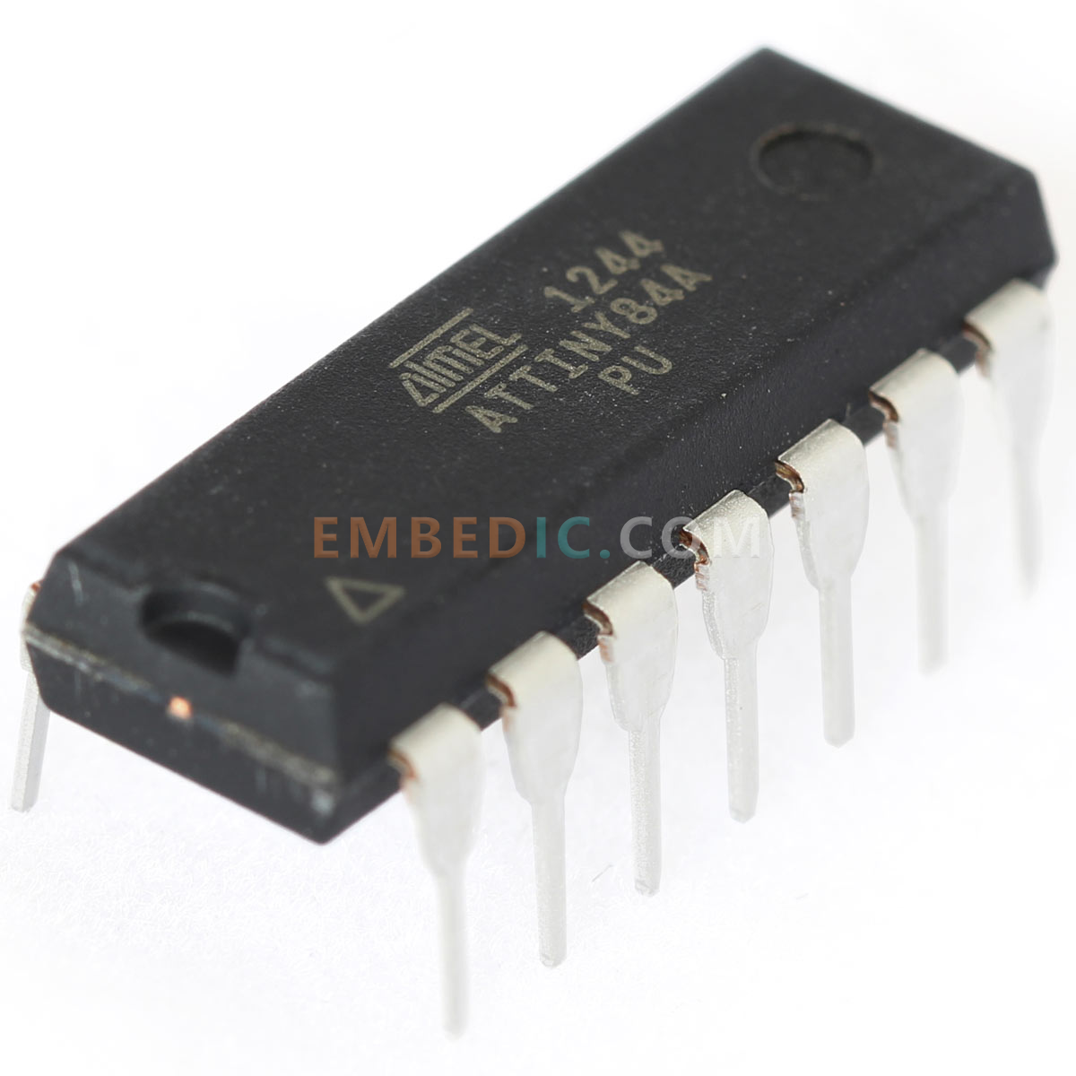
The ATtiny84A microcontroller is the main (MCU) of our breadboard LED watches. It is an 8-bit microcontroller with 14 I/O pins, 8kB of flash memory, 512 bytes of SRAM, and 512 bytes of EEPROM.The ATtiny84A microcontroller is programmed using ArduinoIDE, which makes it easy to upload code to the microcontroller.
The STNS01IC is a programmable reference voltage source and voltage monitoring device (PSU - Power Supply Unit) manufactured by STMicroelectronics with a built-in LDO (Low Dropout Regulator). It is a precision reference voltage source with low dropout and accurate output voltage, programmable through the I2C interface.
The STNS01 is available in a 6-pin SOT23 package and is designed for use in space-constrained applications including battery-powered systems, power management and sensor networks as a voltage monitor to detect over- or under-voltage conditions in the system. (The circuit diagram of the PSU unit used in this project is shown below).
A 7-segment LED display is an electronic display that uses seven LEDs arranged in the shape of the number "8" to display numbers. Each LED is labeled "a" through "g" and when a particular combination of LEDs lights up, it forms a number.
The QDSP-6064 Bubble Display is an LED display, also known as a "bubble display", for battery-powered devices. It is a 7-segment display that uses gas-filled bubbles to illuminate each segment. The display consists of four digits with seven segments per digit plus a decimal point.
A crystal oscillator is an electronic circuit that produces a precise, stable frequency. It is used in our breadboard LED watches to provide a precise timing reference for the microcontroller.
Schottky diodes are used in voltage clamp and voltage regulation circuits and can be used to prevent voltage spikes and protect sensitive electronic components from damage. In this circuit, the Schottky diode drops and regulates the voltage to protect the LED segment display from potential damage.
The 3V.1 lithium polymer battery is a rechargeable lithium ion polymer battery with a nominal voltage of 3.1 volts. Small lithium polymer batteries are widely used in portable electronic devices such as smartphones, tablets and laptops due to their high energy density, low self-discharge rate and long cycle life.
Resistors are electronic components that resist the flow of current. They are used in our breadboard LED watches to limit the current flowing through the LED and create a voltage divider.
A breadboard is a prototype board that allows you to create electronic circuits without soldering. It has rows of holes for electrical connections into which you can insert electronic components and jumpers to create circuits.
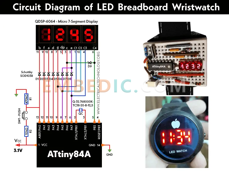
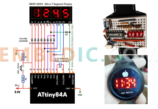
LED breadboard watch circuit diagram.
Circuit diagram of a PSU (Power Supply Unit) charger connected to a 3.1V battery and breadboard.
 charger.png)
The full firmware source code for the breadboard watch can be downloaded from GitHub. You can build and refresh the code using Linux. more details on the GitHub page.
Building the Breadboard LED watch:
Step 1: Connecting the Components
To build the breadboard LED watch, we will first connect the components to the breadboard. First, plug the ATtiny84A microcontroller into the test board, making sure it is oriented correctly. Next, connect the crystal oscillator to pins 1 and 2 of the microcontroller and the two 22pF ceramic capacitors to the crystal leads and ground. Connect two 100nF ceramic capacitors between VCC and GND. Connect a 1k resistor between pin 10 and VCC, and a 13 ohm resistor between pin 220 and the anode of the LED display. Finally, connect the cathode of the LED display to GND.
Step 2: Programming the Microcontroller
After connecting the components, it is time to program the microcontroller. First, download and install ArduinoIDE from the official website.Next, follow the instructions on the official Github repository to install the ATtiny core for Arduino. After installing the core, select "ATtiny84" as the development board and "USBtinyISP" as the programmer in ArduinoIDE. Then, copy and paste the code from GitHub.
Step 3: Power up the circuit
To power the breadboard LED watch, connect a 3.1V Li-Polymer battery to pads J5 and J6 of the PSU (Power Supply Unit). Now connect the battery output to 3.4V through pads J3 and J1 for the test board. Make sure that the positive (+) and negative (-) terminals of the battery holder are connected to the correct pins on the microcontroller and LED display.
Step 4: Setting the Time
When the circuit is energized, the LED display should show the time in hours and minutes. To set the time, press and hold the button connected to microcontroller pin 4. The minute digits will begin to flash and you can use the button to adjust the minutes. Press the button again to move to the hour digit and use the button to adjust the hour. Press the button again to save time and exit the set time mode.
Further Reading: Easy to make a smartwatch based on ATtiny85
In this article, we have provided a comprehensive technical guide on how to build a breadboard LED watch using the ATtiny84A microcontroller. By following these steps, you can create a functional and innovative electronic product that displays time in hours and minutes on a 7-segment LED display. This project is a great way to learn about microcontrollers, electronics, and programming that can be customized and expanded in many ways.

Manufacturer: Texas Instruments
IC DGTL MEDIA PROCESSR 684FCBGA
Product Categories: DSP
Lifecycle:
RoHS:
Manufacturer: Texas Instruments
IC DGTL MEDIA PROCESSR 1031FCBGA
Product Categories: DSP
Lifecycle:
RoHS:
Manufacturer: Texas Instruments
IC DSP FIX/FLOAT POINT 625FCBGA
Product Categories: DSP
Lifecycle:
RoHS:
Manufacturer: Texas Instruments
IC DSP FIX/FLOAT POINT 841FCBGA
Product Categories: DSP
Lifecycle:
RoHS:
Looking forward to your comment
Comment
1
2
3
4
5
6
 Popular Searches
8 Bit MCU, Flash, PIC16 Family PIC16F7XX Series Microcontrollers, 20 MHz, 7 KB, 192 Byte, 44 Pi...
EEPROM 2K 256 X 8 2.5V SERIAL EE IND
System-On-Modules - SOM RCM2200
32-bit Arm Cortex-A53 vision processor with ISP, powerful 3D GPU, dual APEX-2 vision accelerat...
IC MCU 8BIT 60KB FLASH 44QFP
DSP 20MHZ 44QFP
Product updates, events, and resources in your inbox


Smart System

Traffic Management

Security

Consumer Electronics

Wireless Technology

Robot

Internet of Things

Industrial Control