Hello! Welcome to Embedic!
Measuring voltage is an essential task in many microcontroller-based applications. However, most microcontroller ADCs have a maximum input voltage that is limited to the VCC voltage. This limitation can make it challenging to measure voltages higher than the VCC voltage, such as VCC battery voltage over 6V.
Accurate VCC measurement is crucial for many battery-powered applications, as it allows microcontrollers to monitor the battery level and take appropriate actions in case of voltage drops or spikes. In this article, we will explore various methods of measuring VCC battery voltage over 6V using the MCU ADC and discuss the advantages and disadvantages of each method.
MCU ADC stands for Microcontroller Unit Analog-to-Digital Converter. It is a hardware component found in microcontrollers that allows the microcontroller to convert analog signals into digital signals.
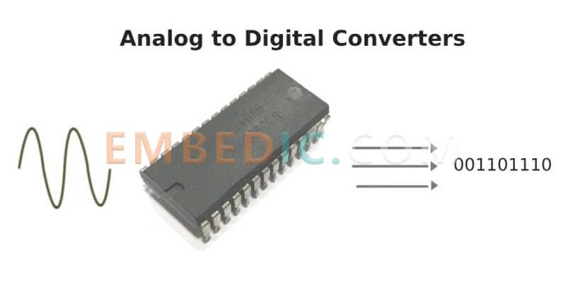
Analog signals are continuous signals, such as sound waves or temperature readings, that vary continuously over time. Digital signals, on the other hand, are discrete signals that are represented using binary values of 0s and 1s.
The ADC allows the microcontroller to measure the analog signals and convert them into digital values that can be processed by the microcontroller. This is useful in a wide range of applications, such as sensor reading, data acquisition, and control systems.
The MCU ADC typically has a certain number of channels, each of which can measure an analog input signal. The resolution of the ADC determines the number of digital values that can be generated for a given analog input range. The higher the resolution, the more accurate the conversion.
Overall, the MCU ADC is an important feature of microcontrollers that enables them to interface with the analog world and perform a wide range of tasks.
Suppose the power supply of MCU is 3.3V and the voltage range that ADC can measure is 0-3.3V, what should we do if we want to measure such scenario as battery voltage of 6V?
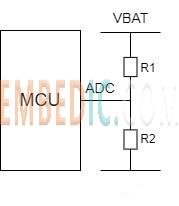
The easy way to think of is to perform resistive voltage dividing first, dividing the voltage higher than 3.3V into the range of the ADC for acquisition, and then finally converting back to the actual voltage. This introduces the question, how large should the voltage divider be? For example, for 1/2 voltage division, should we choose two 1KΩ series or two 1MΩ series? Can the resistor value be chosen at will?
First of all, the conclusion: the resistor can not be chosen arbitrarily, first of all it can not be too big!
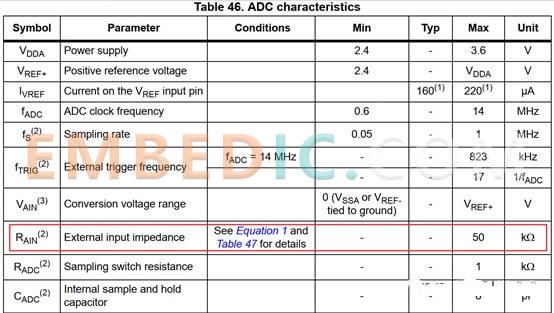
Take STM32F103 as an example, you can see in the datasheet that the external input impedance has a maximum value of 50kΩ.
This value is calculated by the following formula.
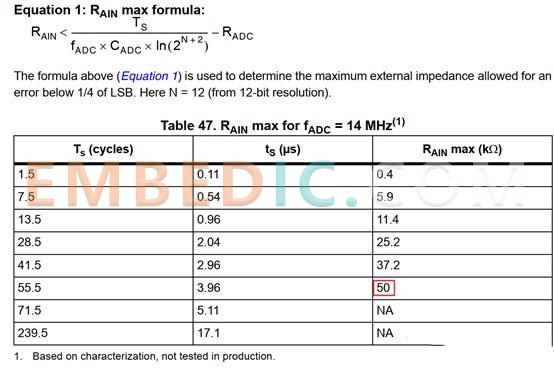
It should be noted that the maximum value of the input impedance is not fixed, not that as long as it is less than 50kΩ, because it has a relationship with the ADC clock frequency, sampling period, and the number of conversion bits. For example, in the table above, when the ADC clock frequency is 14Mhz, the sampling period is 1.5 cycels, and the number of conversion bits is 12, the maximum input impedance is 0.4kΩ.
Tab 46 nominal maximum input impedance 50kΩ, is in the ADC clock frequency 14Mhz, sampling period 55.5 cycles, conversion bit number 12 calculated value, it is also the ADC module can accept the maximum value (by the hardware decision, which is why Tab 47 last two lines to write NA reason, although according to the formula can also be calculated out of a greater value than 50 ).
In simple terms, it can be understood as follows: because the ADC internal sample-hold circuit (composed of capacitors), if the outside resistance is large, it will lead to a long charging time of the RC circuit, and if the sampling period is small, it will cause the capacitor to be collected without being fully charged, and naturally the number obtained by the ADC will not be allowed.
From the perspective of improving the ADC sampling rate, the smaller the resistance, the faster the RC charging and discharging, the higher the sampling rate of the ADC can be. However, the small resistance will increase the power consumption, in the power consumption requirements of the occasion, the resistance can not be selected too small.
For must low input impedance, but also the need for low-power occasions, you can first use a large resistor voltage division, followed by the op-amp follower way.
After the problem of resistor size, there is one last question, what is the relationship between the equivalent input impedance and the two series voltage divider resistors in the first picture? Is the equivalent input impedance R1, or the series value R1+R2, or the parallel value R1*R2/R1+R2? This problem has confused me for a long time, when the theoretical knowledge learned in school all handed over to the teacher.
This problem can be so simple to think, assume R2 is 0Ω, the voltage into the ADC is GND, and R1 is how big it does not matter, the equivalent input impedance is 0Ω. and then assume R2 infinity, and so is disconnected, the resistance is only R1. So think about the answer is clear, the equivalent input impedance is the parallel connection of two voltage divider resistors.
In conclusion, measuring VCC battery voltage over 6V is an essential task for many microcontroller-based applications, and the MCU ADC is a vital component for achieving this. There are several methods to measure VCC battery voltage over 6V, including using a voltage divider circuit, an external ADC, or an internal voltage reference.
Each method has its advantages and disadvantages, and the choice of method depends on the specific application requirements and design constraints. With careful consideration of the circuitry and programming, accurate VCC measurement can be achieved, enabling microcontrollers to monitor battery levels and take appropriate actions. As microcontrollers continue to play an essential role in many industries, accurate VCC measurement will remain an important consideration for many applications.

Manufacturer: Texas Instruments
IC DGTL MEDIA PROCESSR 1031FCBGA
Product Categories: DSP
Lifecycle:
RoHS:
Manufacturer: Microchip
IC MCU 8BIT 28KB FLASH 40UQFN
Product Categories: 8bit MCU
Lifecycle:
RoHS:
Manufacturer: Texas Instruments
IC DSP FIX/FLOAT POINT 176HLQFP
Product Categories: DSP
Lifecycle:
RoHS:
Manufacturer: STMicroelectronics
IC MCU 32BIT 16KB FLASH 48LQFP
Product Categories: 32bit MCU
Lifecycle:
RoHS:
Looking forward to your comment
Comment
1
2
3
4
5
6
 Popular Searches
8 Bit MCU, Flash, PIC16 Family PIC16F7XX Series Microcontrollers, 20 MHz, 7 KB, 192 Byte, 44 Pi...
EEPROM 2K 256 X 8 2.5V SERIAL EE IND
System-On-Modules - SOM RCM2200
32-bit Arm Cortex-A53 vision processor with ISP, powerful 3D GPU, dual APEX-2 vision accelerat...
IC MCU 8BIT 60KB FLASH 44QFP
DSP 20MHZ 44QFP
Product updates, events, and resources in your inbox


Smart System

Traffic Management

Security

Consumer Electronics

Wireless Technology

Robot

Internet of Things

Industrial Control


