Hello! Welcome to Embedic!
This solution uses the NXP JN518x series of ZigBee 2.4 G wireless RF chips. Compared with similar products in the market, JN5189 has higher performance, lower power consumption, lower prices, and more complete technical development materials. The mainstream JN5169 series of NXP has The first choice of many large smart device manufacturers.
This solution uses NXP’s latest JN518x series chips. Compared with the previous product JN5169, both performance and power consumption have been greatly improved. With NXP’s stable ZigBee underlying protocol stack and perfect application layer architecture, customers can only A simple application layer development can quickly complete a ZigBee project, which greatly shortens the project development cycle.
This solution is based on a router with relay function based on JN5189. As a relay router, it can also be used as a smart lantern to add color to the smart home. With the mobile phone APP, you can remotely control the lights on and off, control other smart home devices connected to the relay router, whether your smart home device is in the corner of your home, it can be completely covered, allowing you to enjoy opening the door , Is the shining of warm light.
With the improvement of consumption levels, more and more people are beginning to use smart home devices, and more and more well-known manufacturers are entering the field of smart home. In order to manage as few as 2-3, as many as 100-200 smart home devices in each household, a huge data transmission network is needed to transmit the information of each device to the user's mobile APP for management in time.
The current mainstream wireless transmission technologies: ZigBee, BLE, and Wifi are all used in the field of smart homes, but BLE and Wifi have more or less inherent defects in the application of smart homes. BLE only supports point-to-point transmission, and cannot transmit such huge multi-node data at the same time. It is only suitable for some applications with complex functions and need to be directly connected to a mobile phone.
The transmission distance is short and cannot be extended in topology. Wifi significantly surpasses BLE and ZigBee technologies in power consumption, and has advantages in applications that transmit large amounts of data. However, it is not suitable for smart devices with low data traffic and low power consumption requirements.
A battery needs to be used for one year of smart devices. However, since the birth of ZigBee technology, low power consumption, self-organizing network, and topology extension are its advantages. Using the relay routing application of this solution, it can easily extend hundreds of meters to cover every corner of the home.
At the same time, it can be used as a smart color light and controlled by the mobile phone APP to light up every darkness in the home.
This relay routing scheme is to provide a relay node for some smart devices that are far away from the home gateway, so that these smart devices can be connected to the home gateway smoothly, so that users can use the smart device stably.
The general application scenario is as follows: A three-story villa, the home gateway is generally placed on the first floor, and a user’s smart light A is placed in a three-story room. Because the transmission environment is affected by the wall and distance, the smart light A may be difficult Link to the home gateway.
If the user wants to turn on the light remotely, it will fail. At this time, placing a router repeater of this solution on the second floor can link the smart light A to the repeater and the repeater to the home gateway to forward control information so that the user can successfully turn on the light. At the same time, the colored lights on the router relay can also be controlled by the user, so that the lights on the second floor can also be turned on.
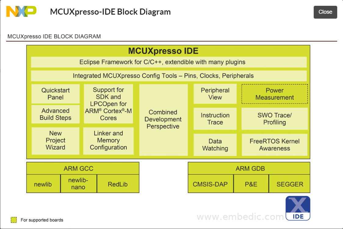
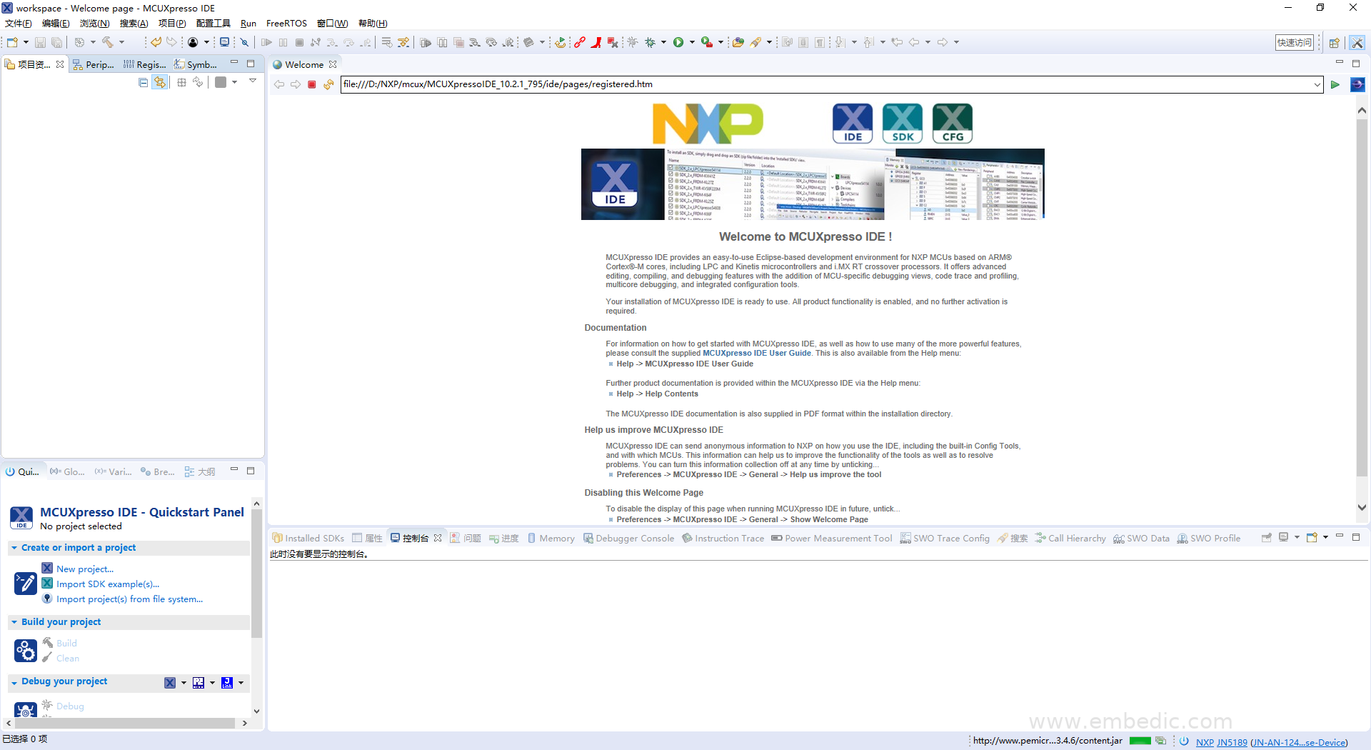
XP JN5189 uses the free IDE MCUXpresso provided by NXP as the basic development environment. MCUXpresso is a convenient and easy-to-use IDE based on the open source development platform Eclipse for customization and optimization, and is well received by many NXP chip developers.
MCUXpresso can be downloaded from NXP official website:
https://www.nxp.com/design/software/development-software/mcuxpresso-software-and-tools/mcuxpresso-integrated-development-environment-ide:MCUXpresso-IDE
NXP provides the Customer Module Evaluation Tool (CMET), and CMET provides 14 test modes:
Overview:
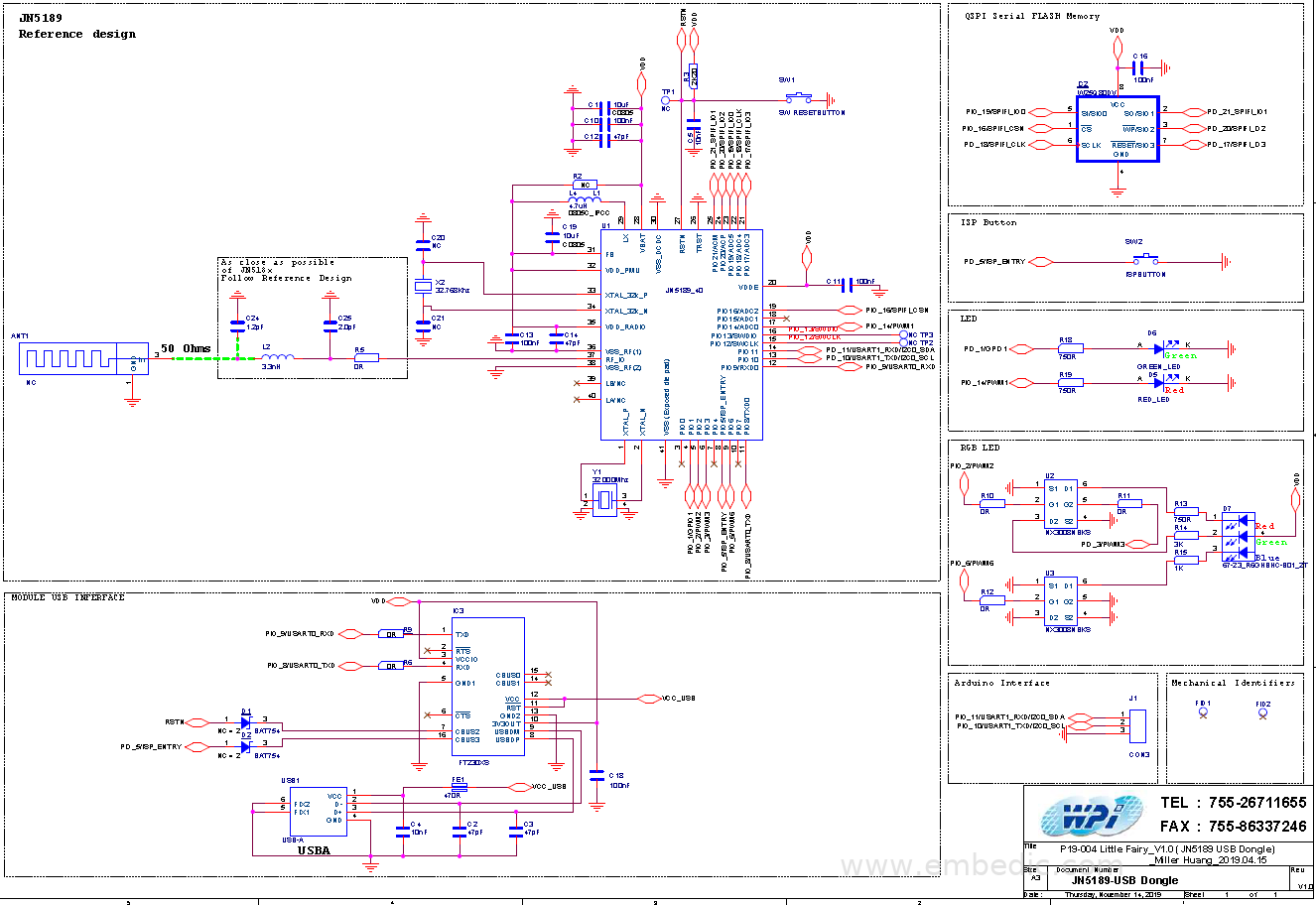
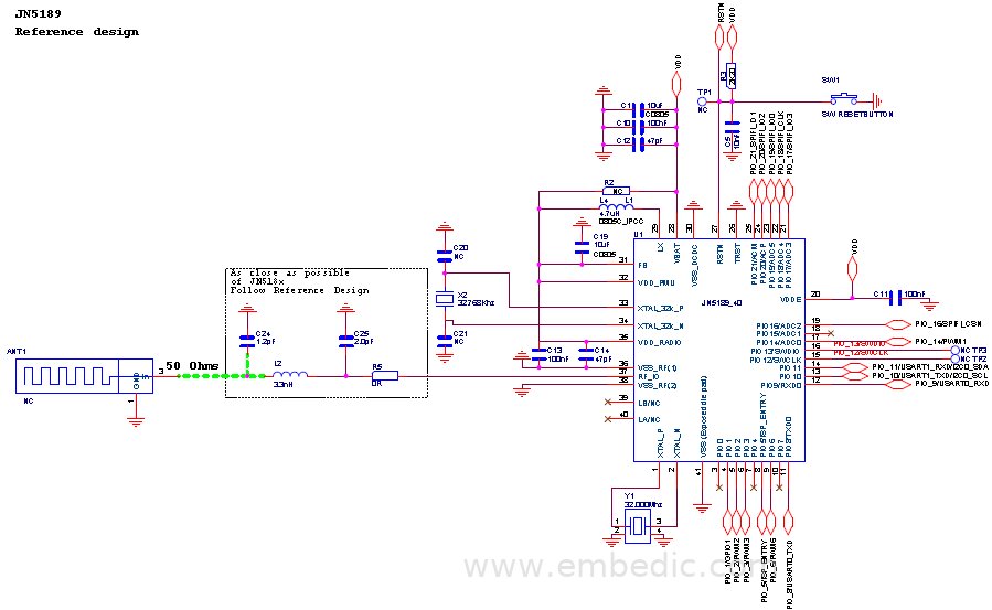
JN5189 minimum system:
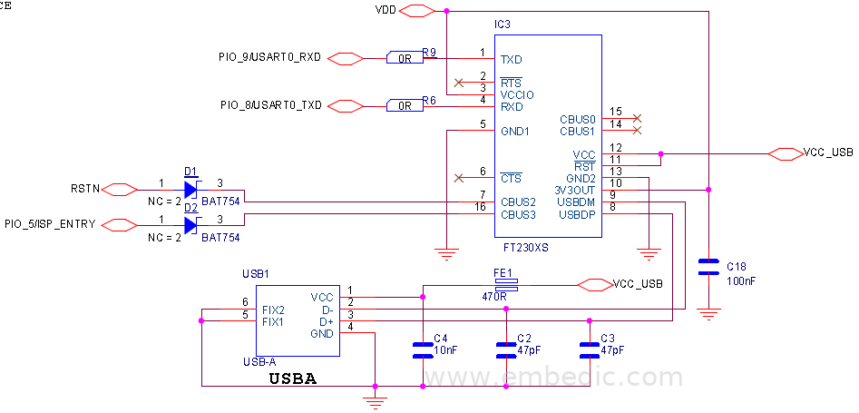
Serial port download and debug circuit:
Realize USB to UART through FT230XS. Supports downloading programs to JN5189, and supports serial port printing and debugging.
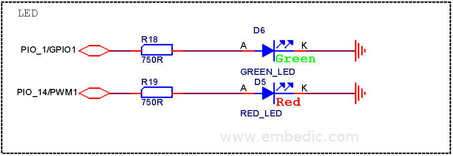
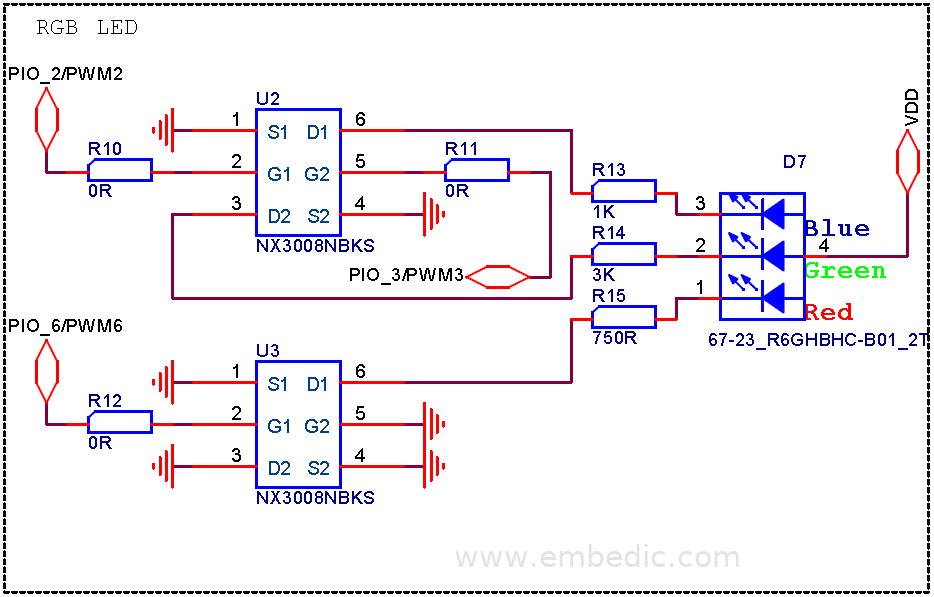
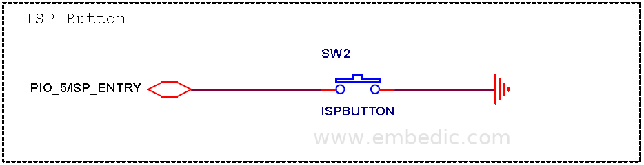
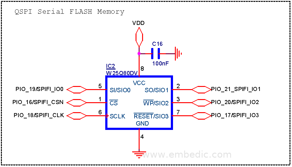
It is composed of QSPI Flash, LEDs and Buttons.
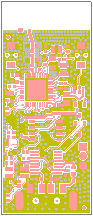
Scheme PCB circuit diagram
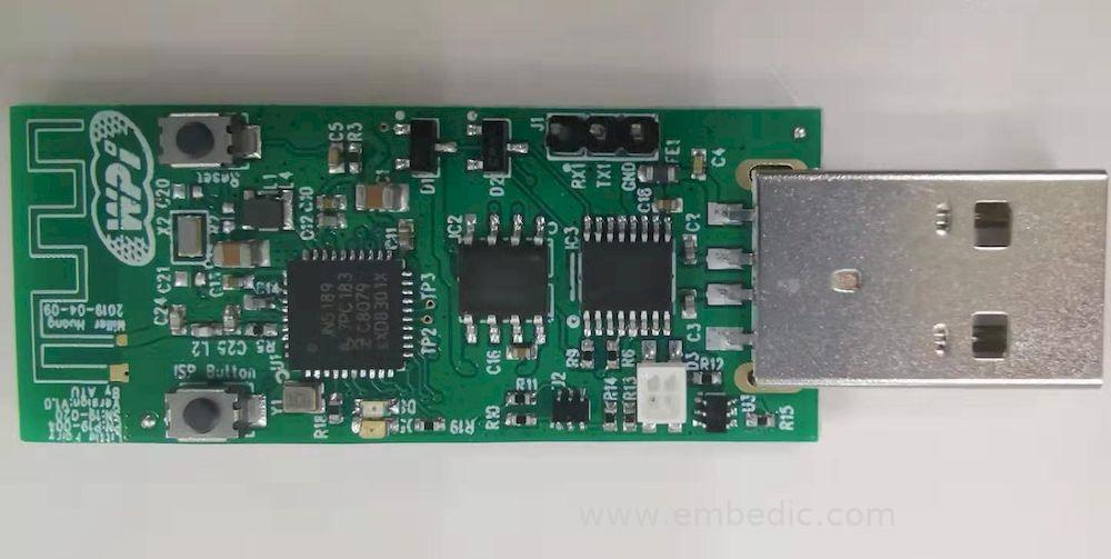
► Showcase photos
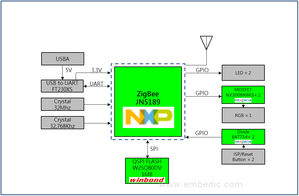
► Scheme block diagram
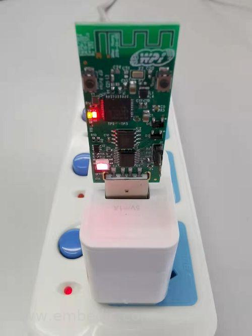
► Demo power-up diagram
► Core technical advantages
1. The JN518x series is the latest ultra-low power consumption, high performance, Cortex-M4 wireless microcontroller launched by NXP.
2. 32-bit core, up to 48 MHz frequency.
3. Support ZigBee 3.0, IEEE802.15.4 protocol stack.
4. Contains 2.4 GHz IEEE802.15.4 wireless transceiver and a wealth of general digital and analog peripherals.
5. Wireless transceiver mode with ultra-low current consumption.
6. JN5189/JN5189T has 640 KB Flash and 152 KB RAM.
7. JN5188/JN5188T has 320 KB Flash and 88 KB RAM.
8. JN5188T/JN5189T integrates NFC tag internally, and NTAG application can be realized by connecting NFC antenna.
► Solution specifications
1. Chip: NXP ZigBee JN5189
2. Frequency: 2.405 GHz ~ 2.480 GHz
3. Transmitting power: 10 dBm (Max)
4. Receiving sensitivity: -100 dBm
5. Working voltage: 1.9 V ~ 3.6 V
6. Transmission distance: 200 m (Max)
7. Working temperature: -40 ℃ ~ 125 ℃
8. Current consumption: transmit 20.3 mA (+10 dbm), receive 4.3 mA, sleep 350 nA
9. Package: QFN40-0.5mm
IC MCU 16BIT 64KB FLASH 64TQFP

IC MCU 32BIT 256KB FLASH 64LQFP

IC MCU 16BIT 64KB FLASH 38SSOP

IC MCU 16BIT 64KB FLASH 100LQFP
1
2
3
4
5
6


Product updates, events, and resources in your inbox


Smart System

Traffic Management

Security

Consumer Electronics

Wireless Technology

Robot

Internet of Things

Industrial Control