Hello! Welcome to Embedic!
In this paper, an STM32-based unmanned vending machine system is designed to address the shortcomings of existing vending machines.
With the development of technology and the improvement of living standards, people's requirements for shopping experience are getting higher and higher. Traditional shopping malls and supermarkets can no longer meet the needs of consumers, so unmanned vending machines have emerged. In this paper, an STM32-based unmanned vending machine system is designed to address the shortcomings of existing vending machines.
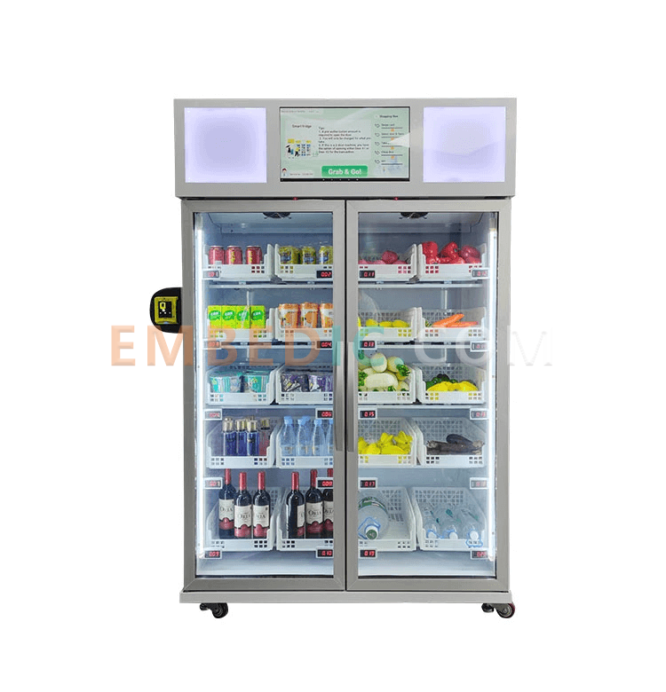
The system adopts STM32 as the main control chip and uses an LCD screen to display the inventory and price of various products, and the user presses the corresponding button to select the specified product and enters the account password in the matrix keyboard to pay. If the payment is successful, the corresponding motor rotates at a certain angle to make the goods out of the warehouse and modify the inventory at the same time; if the balance is insufficient, the sound and light prompts are made. The cell phone can also view the consumption flow, commodity inventory, and carry out replenishment and recharge operations.
The core component of the system is the STM32 main control chip, which is responsible for the control and management of the whole vending machine. The LCD screen is used to display product information, prices, etc. The matrix keyboard is used for users to enter their account passwords for payment. The motor control board is used to control the goods out of the warehouse.
Hardware composition:
The software part mainly includes STM32 program and mobile APP program. STM32 program is the core program of the vending machine, responsible for controlling the work of each component and realizing the basic functions of the vending machine. APP program can communicate with STM32 to realize the functions of product inventory view, replenishment and recharge, etc.
The STM32 part is mainly divided into the following modules:
(1) Initialization module: initialize the working state and parameters of each component.
(2) Product selection module: select the corresponding product according to the button pressed by the user.
(3) Payment module: Enter the account password through the matrix keyboard to make payment, and control the working state of the motor according to the payment result.
(4) Inventory management module: according to the sales of goods, real-time update of commodity inventory information.
(5) Sound and light prompting module: sound and light prompting through buzzer and LED light when user's payment fails or balance is insufficient.
The mobile APP program is mainly divided into the following modules:
(1) User login module: Users can login to the APP by entering their account password.
(2) Commodity view module: Users can view the inventory of commodities in the vending machine.
(3) Replenishment module: merchants can replenish goods to the specified quantity through the APP.
(4) Recharge module: Users can recharge their accounts through APP.
(5) Consumption flow module: Users and merchants can view the consumption records of the vending machine.
The above modules communicate with each other through STM32 and APP program to realize the function of the whole system.
The following is the code of the 28BYJ48 stepper motor:
(1) Define some macros and variables to facilitate control of the stepper motor:
#define IN1 GPIO_Pin_0
#define IN2 GPIO_Pin_1
#define IN3 GPIO_Pin_2
#define IN4 GPIO_Pin_3
#define STEPS_PER_REVOLUTION 2048 //
#define DELAY_MS 5 //
GPIO_InitTypeDef GPIO_InitStructure;
int step_count = 0;
uint16_t steps[] = {IN1 | IN2 | IN3 | IN4,
IN2 | IN3 | IN4,
IN1 | IN2 | IN3,
IN3 | IN4,
IN1 | IN3 | IN4,
IN2 | IN4,
IN1 | IN2,
IN4};
void delay_ms(uint32_t ms) {
uint32_t i, j;
for (i = 0; i < ms; i++) {
for (j = 0; j < 1141; j++);
}
}
void setStep(int step) {
GPIO_ResetBits(GPIOB, IN1 | IN2 | IN3 | IN4);
GPIO_SetBits(GPIOB, steps[step]);
}
void forward(int steps_to_move) {
int i;
for (i = 0; i < steps_to_move; i++) {
setStep(step_count % 8);
step_count++;
delay_ms(DELAY_MS);
}
}
void backward(int steps_to_move) {
int i;
for (i = 0; i < steps_to_move; i++) {
setStep(step_count % 8);
step_count--;
delay_ms(DELAY_MS);
}
}
In the above code, four pins are defined to control the stepper motor, and then some functions are defined to achieve forward and reverse control.
The delay_ms function is used to delay the speed of the control stepper motor. the STEPS_PER_REVOLUTION macro defines the number of steps per revolution, and the DELAY_MS macro defines the delay time to control the speed.
The setStep function sets the pin state according to the number of steps passed in, then the forward and backward functions control the direction of rotation of the stepper motor according to the number of steps to be moved, respectively, and call the setStep function to control the number of steps of the stepper motor.
Finally, the forward and backward functions are encapsulated into a sub-function to make it easier to call:
void control_stepper_motor(int steps_to_move, int direction) {
if (direction == 1) {
forward(steps_to_move);
} else {
backward(steps_to_move);
}
}
In this way, you can control the 28BYJ48 stepper motor by calling the control_stepper_motor function to achieve forward and reverse rotation.
The following is the sample code of 4x4 capacitive matrix keyboard:
(1) Define some macros and variables in order to control the capacitive matrix keyboard:
#define ROW1 GPIO_Pin_0
#define ROW2 GPIO_Pin_1
#define ROW3 GPIO_Pin_2
#define ROW4 GPIO_Pin_3
#define COL1 GPIO_Pin_4
#define COL2 GPIO_Pin_5
#define COL3 GPIO_Pin_6
#define COL4 GPIO_Pin_7
GPIO_InitTypeDef GPIO_InitStructure;
const uint8_t keys[4][4] = {
{'1', '2', '3', 'A'},
{'4', '5', '6', 'B'},
{'7', '8', '9', 'C'},
{'*', '0', '#', 'D'}
};
In the above code, 8 pins are defined to control the capacitive matrix keyboard, and a two-dimensional array is used to store the characters corresponding to each key.
(2) A function needs to be written to detect if the capacitive matrix keyboard is pressed.
This function needs to scan the keyboard by polling to detect the key presses and return the character corresponding to the key if there is a key press:
char scan_keypad() {
GPIO_ResetBits(GPIOC, ROW1 | ROW2 | ROW3 | ROW4);
GPIO_SetBits(GPIOC, COL1 | COL2 | COL3 | COL4);
if (GPIO_ReadInputDataBit(GPIOC, ROW1) == 0) {
while (GPIO_ReadInputDataBit(GPIOC, ROW1) == 0);
return keys[0][0];
} else if (GPIO_ReadInputDataBit(GPIOC, ROW2) == 0) {
while (GPIO_ReadInputDataBit(GPIOC, ROW2) == 0);
return keys[1][0];
} else if (GPIO_ReadInputDataBit(GPIOC, ROW3) == 0) {
while (GPIO_ReadInputDataBit(GPIOC, ROW3) == 0);
return keys[2][0];
} else if (GPIO_ReadInputDataBit(GPIOC, ROW4) == 0) {
while (GPIO_ReadInputDataBit(GPIOC, ROW4) == 0);
return keys[3][0];
}
GPIO_ResetBits(GPIOC, ROW1 | ROW2 | ROW3 | ROW4);
GPIO_SetBits(GPIOC, COL1 | COL2 | COL3 | COL4);
if (GPIO_ReadInputDataBit(GPIOC, ROW1) == 0) {
while (GPIO_ReadInputDataBit(GPIOC, ROW1) == 0);
return keys[0][1];
} else if (GPIO_ReadInputDataBit(GPIOC, ROW2) == 0) {
while (GPIO_ReadInputDataBit(GPIOC, ROW2) == 0);
return keys[1][1];
} else if (GPIO_ReadInputDataBit(GPIOC, ROW3) == 0) {
while (GPIO_ReadInputDataBit(GPIOC, ROW3) == 0);
return keys[2][1];
} else if (GPIO_ReadInputDataBit(GPIOC, ROW4) == 0) {
while (GPIO_ReadInputDataBit(GPIOC, ROW4) == 0);
return keys[3][1];
}
GPIO_ResetBits(GPIOC, ROW1 | ROW2 | ROW3 | ROW4);
GPIO_SetBits(GPIOC, COL1 | COL2 | COL3 | COL4);
if (GPIO_ReadInputDataBit(GPIOC, ROW1) == 0) {
while (GPIO_ReadInputDataBit(GPIOC, ROW1) == 0);
return keys[0][2];
} else if (GPIO_ReadInputDataBit(GPIOC, ROW2) == 0) {
while (GPIO_ReadInputDataBit(GPIOC, ROW2) == 0);
return keys[1][2];
} else if (GPIO_ReadInputDataBit(GPIOC, ROW3) == 0) {
while (GPIO_ReadInputDataBit(GPIOC, ROW3) == 0);
return keys[2][2];
} else if (GPIO_ReadInputDataBit(GPIOC, ROW4) == 0) {
while (GPIO_ReadInputDataBit(GPIOC, ROW4) == 0);
return keys[3][2];
}
GPIO_ResetBits(GPIOC, ROW1 | ROW2 | ROW3 | ROW4);
GPIO_SetBits(GPIOC, COL1 | COL2 | COL3 | COL4);
if (GPIO_ReadInputDataBit(GPIOC, ROW1) == 0) {
while (GPIO_ReadInputDataBit(GPIOC, ROW1) == 0);
return keys[0][3];
} else if (GPIO_ReadInputDataBit(GPIOC, ROW2) == 0) {
while (GPIO_ReadInputDataBit(GPIOC, ROW2) == 0);
return keys[1][3];
} else if (GPIO_ReadInputDataBit(GPIOC, ROW3) == 0) {
while (GPIO_ReadInputDataBit(GPIOC, ROW3) == 0);
return keys[2][3];
} else if (GPIO_ReadInputDataBit(GPIOC, ROW4) == 0) {
while (GPIO_ReadInputDataBit(GPIOC, ROW4) == 0);
return keys[3][3];
}
return '�';
}
In the above code, the keyboard is scanned using polling. First, all row pins are set low and all column pins are set high, and it detects whether a key is pressed. If a key is pressed, the character corresponding to that key is returned. Next, the scan_keypad function can be called cyclically in the main function to read the key values:
int main(void) {
char key = '�';
RCC_APB2PeriphClockCmd(RCC_APB2Periph_GPIOC, ENABLE);
RCC_APB2PeriphClockCmd(RCC_APB2Periph_GPIOB, ENABLE);
GPIO_InitStructure.GPIO_Pin = ROW1 | ROW2 | ROW3 | ROW4;
GPIO_InitStructure.GPIO_Mode = GPIO_Mode_Out_PP;
GPIO_InitStructure.GPIO_Speed = GPIO_Speed_50MHz;
GPIO_Init(GPIOC, &GPIO_InitStructure);
GPIO_InitStructure.GPIO_Pin = COL1 | COL2 | COL3 | COL4;
GPIO_InitStructure.GPIO_Mode = GPIO_Mode_IPU;
GPIO_InitStructure.GPIO_Speed = GPIO_Speed_50MHz;
GPIO_Init(GPIOC, &GPIO_InitStructure);
while (1) {
key = scan_keypad();
if (key != '�') {
//
}
}
}
In the above code, the 8 pins are first initialized and the scan_keypad function is called in a loop to read the key value. If the key value is read, it can be processed accordingly.
In order to verify the feasibility and stability of the system, a series of tests were conducted after the hardware was built.
(1) The overall operation logic of the system was tested. The basic functions of the system were verified by simulating users' selection of goods, payment and shipment. The test results showed that the system could run stably and could meet the users' shopping needs.
(2) The inventory management function of the system was tested. The system's inventory information was verified to be updated in real time by simulating the sales of goods. The test results showed that the system can handle inventory information accurately.
(3) Tested the functions of the APP program on the cell phone. The functions of the APP program were verified by simulating operations such as user login, viewing product inventory, making replenishment, topping up and viewing consumption flow. The test results show that the APP program can run normally and can achieve good communication with the STM32 main control chip.
IC MCU 8BIT 288KB FLASH 52LQFP

IC MPU Q OR IQ 800MHZ 689TEBGA

IC MPU Q OR IQ 667MHZ 561TEBGA1
1
2
3
4
5
6


Product updates, events, and resources in your inbox


Smart System

Traffic Management

Security

Consumer Electronics

Wireless Technology

Robot

Internet of Things

Industrial Control