Hello! Welcome to Embedic!
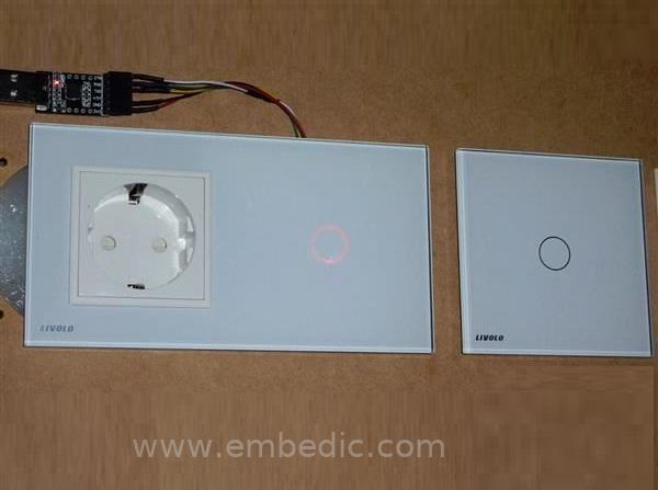
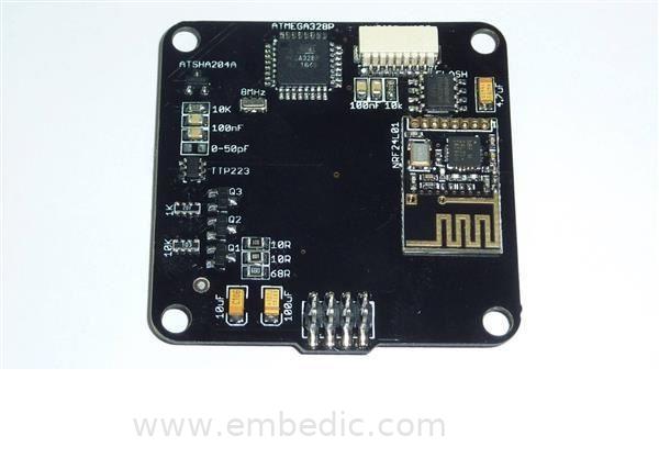
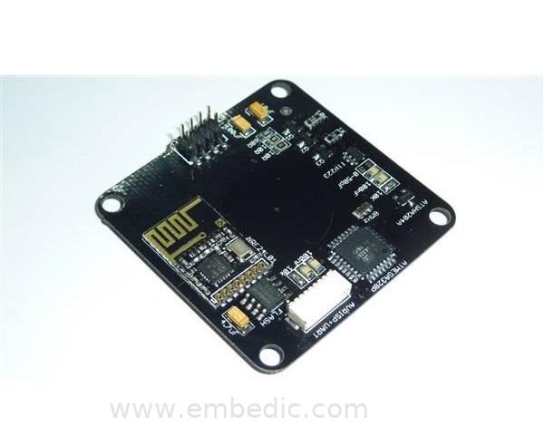
This circuit is a touch switch, which can replace the wall switch, and allows you to control the lighting (turn on and off, I want to make another board to adjust the brightness in the future), using two PCBs, the first one is black, including the microcontroller , Antenna, etc., the second PCB is red, including AC parts, power supplies, relays, etc.
This circuit is a touch switch, which can replace the wall switch, and allows you to control the lighting (turn on and off, I want to make another board to adjust the brightness in the future), using two PCBs, the first one is black, including the microcontroller , Antenna, etc., the second PCB is red, including AC parts, power supplies, relays, etc.
characteristic:
-ATmega328P 3.3V 8Mhz microcontroller with pads for external oscillator (optional)
-Antenna NRF24L01 SMD-
The touch button TTP223 + HTTM photo reflector can interact with the switch manually.
-RGB LED (blue without PWM) indicates the status of the relay or RF connection.
-Flash memory chip for FOTA
-Chip ATSHA204A for signature.
-JST-8-1MM AVRISP + UART programming connector (UART requires 100nF capacitor in the cable)
-2 5A HF46F-5-HS1 relays to control AC load
-DS18B20 sensor near the power supply to control the internal temperature.
-Power HILINK HLK-PM01 5V-
Voltage regulator AMS1117-3.3
Claim:
-The neutral wire must be connected to the power supply.
-You must use a 3D printer to print two pieces of plastic to accommodate the circuit, hold the glass and fix the screws to the wall.

IC MCU 8BIT 16KB FLASH 64LQFP

IC MCU 16BIT 64KB FLASH 80TQFP
IC MCU 16BIT 8KB FLASH 32LQFP
1
2
3
4
5
6


Product updates, events, and resources in your inbox


Smart System

Traffic Management

Security

Consumer Electronics

Wireless Technology

Robot

Internet of Things

Industrial Control