Hello! Welcome to Embedic!
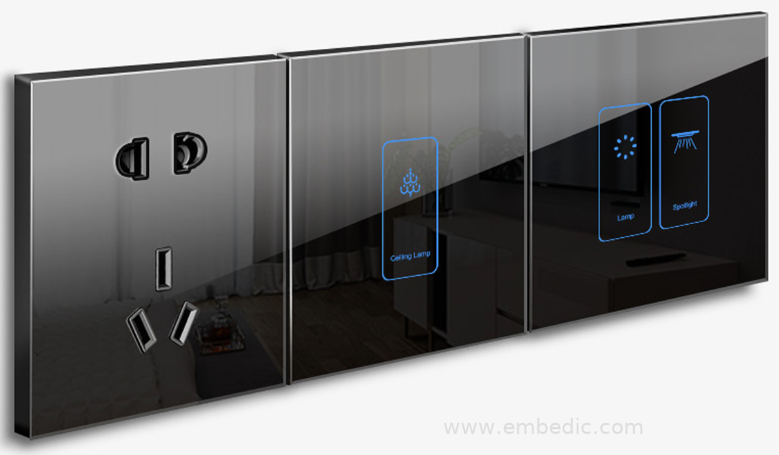
Hotel touch panel functions include card access, lighting control (bathroom lights, gallery lights, desk lamps, etc.), scene modes (bright mode, reading mode, TV mode, sleep mode), curtain and tying curtain switch control, accommodation prompt control , Air-conditioning control and exhaust fan control. At the same time, the control mode data of each room is sent to the central control background so that the front desk staff can understand the room information.
With the improvement of the quality of life, most hotels have implemented smart hotel design models. The one-card room card turns on the power supply mode of the entire room, and the hotel touch panel turns on the smart mode of the entire room.
Hotel touch panel functions include card access, lighting control (bathroom lights, gallery lights, desk lamps, etc.), scene modes (bright mode, reading mode, TV mode, sleep mode), curtain and tying curtain switch control, accommodation prompt control (Do not disturb, check out, cleaning, etc.), air conditioning control and exhaust fan control, and at the same time send the control mode data of each room to the central control background, so that the front desk staff can understand the room information.
This solution mainly introduces Microchip's touch button and proximity sensor touch panel solution. At present, many MCU products such as PIC and Atmel have 1D Touch functions. 1D Touch functions include touch buttons, sliders, scroll wheels, and proximity sensors. This program selects Microchip PIC16LF1599 for design, and supports up to 17 Touch Channels.
Microchip's touch solution can adapt to a variety of abnormally noisy electromagnetic environments through car-level strict ESD/EMI anti-interference capabilities and EMC compatibility, such as operating in thick gloves, stylus, pressure sensing, waterproof and moisture-proof, strong light and other environments.
Before entering the design, first introduce the principle of Microchip's touch solution. PIC16LF1599 uses mTouch technology, through the differential capacitive voltage divider (CVD) method, a simple description is that the finger press causes the capacitance change, thereby detecting the voltage change. CVD is a charge/voltage-based technology that uses only an analog-to-digital converter (ADC) module to measure the relative capacitance on the pin.
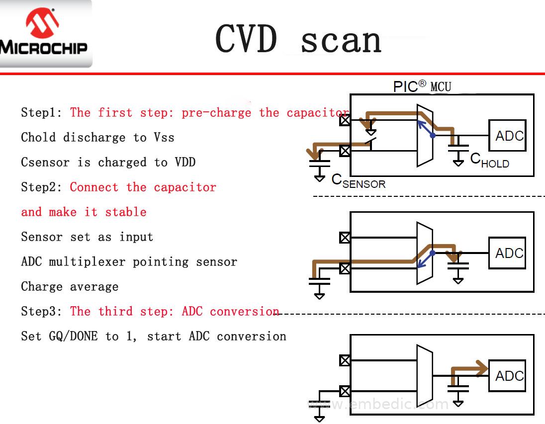
Since only a common PIC device peripheral is needed, this technology can be implemented on most MCUs. This technique performs relative capacitance measurement based on the size of the internal ADC sample and hold capacitance. The specific steps are divided into three steps.
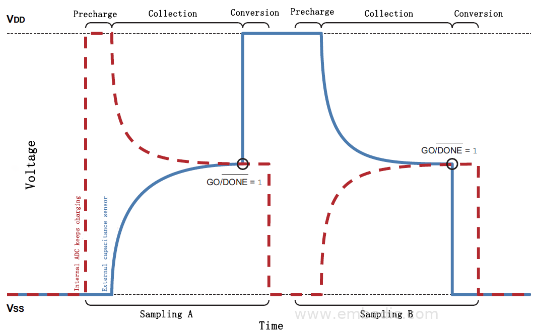
The first step: pre-charge the capacitors, charge the two capacitors to opposite voltages. The first execution is "Sampling A". The second time (introduced in steps 4-6) is "Sampling B".
Step 2: Connect the capacitors and stabilize them, connect the two capacitors in parallel and stabilize the charge. As the external capacitance increases, the initial charge will increase until the internal capacitance does not change, so its charge remains constant.
Step 3: ADC conversion, the final voltage on Chold is determined by the relationship between the size of the external capacitor and the size of the internal capacitor;
Repeat the first to third steps: perform the above operation again, but this time reverse the precharge voltage. The difference between the two results is used as the current sensor reading. The following picture.
Next, introduce the principle of capacitive proximity sensing.
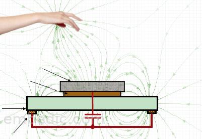
Capacitive proximity sensing detects changes in capacitance on the sensor due to user touch or proximity. For the Microchip solution, the sensor can be any conductive material connected to the pins of the MCU through an optional series resistor.
Generally, any conductive objects or objects with high dielectric constant near the sensor will affect the sensor capacitance. The scanning method of the capacitive proximity sensor is the same as that of the capacitive touch sensor. The device constantly monitors the capacitance of the sensor and waits for a major change to occur.
The change of the proximity signal will be significantly smaller than the change of the touch signal, because it must be effective for a long distance in air (not plastic or glass), which is the most likely electric field medium. In order to maintain reliable detection, the system needs to maintain a good Signal-to-Noise Ratio (SNR). As shown below.
Development and design instructions:
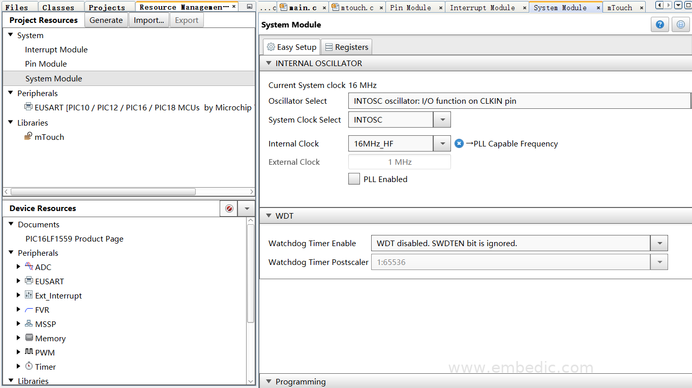
The development environment adopts Microchip MPLAB X IDE, and the operation is carried out through the MCC code configurator. For this part, please refer to my series of blog posts-Microchip Code Configurator MCC Learning Tutorial, which has detailed information on how to operate MCC step by step and use each module function. Illustrated description. We now directly carry out the operation design, and complete the PIC16LF1559 touch solution in a few simple steps.
Step one, system clock configuration;
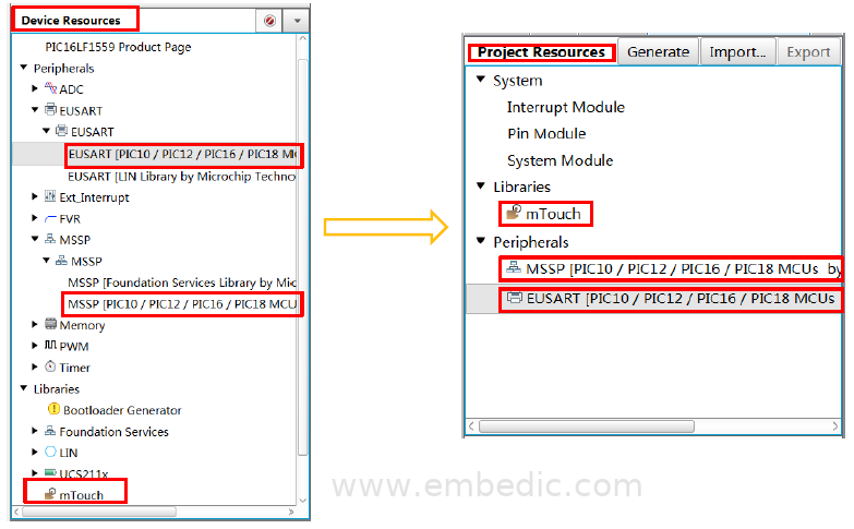
Step two, use MCC to start the Touch and EUSART modules;
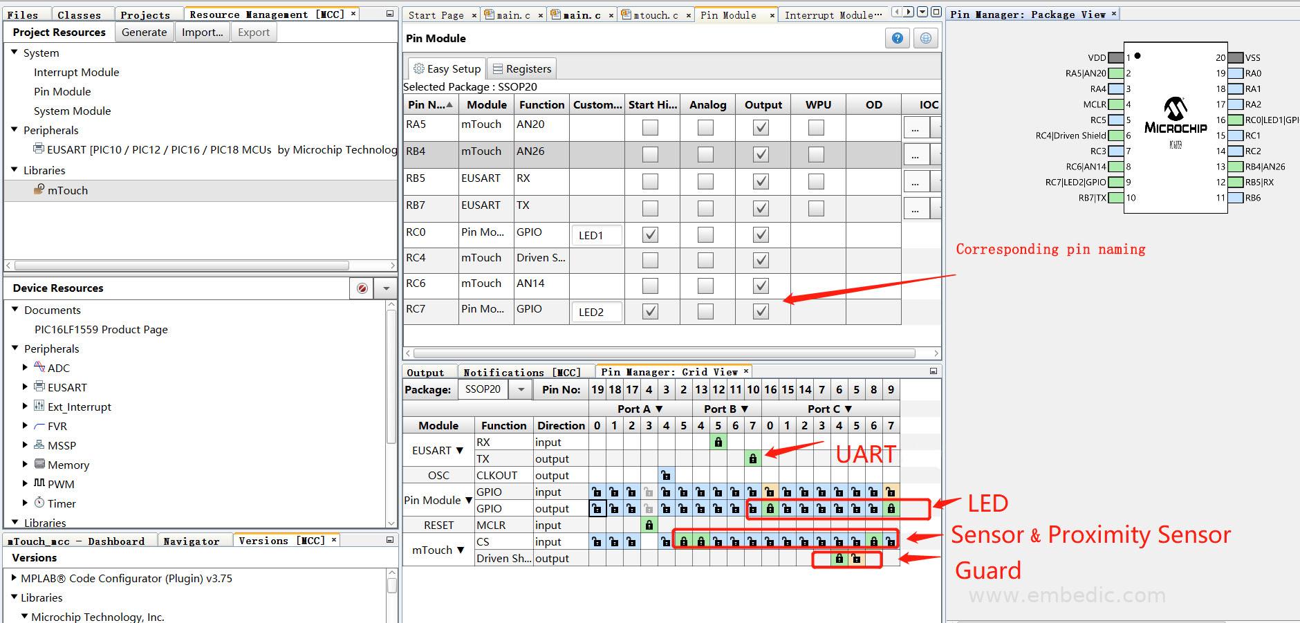
Step three, pin assignment;
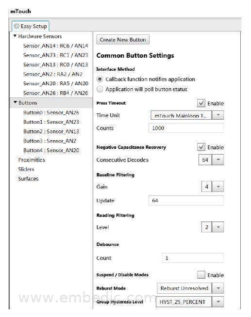
Step four, create Button;
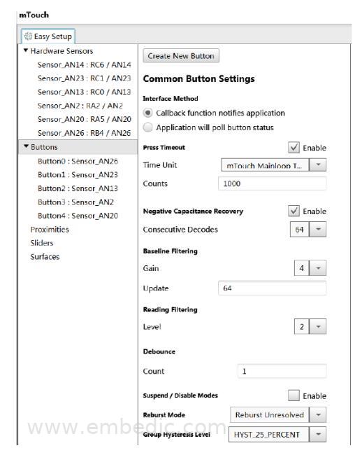
Step 5, Button and Sensor are associated;
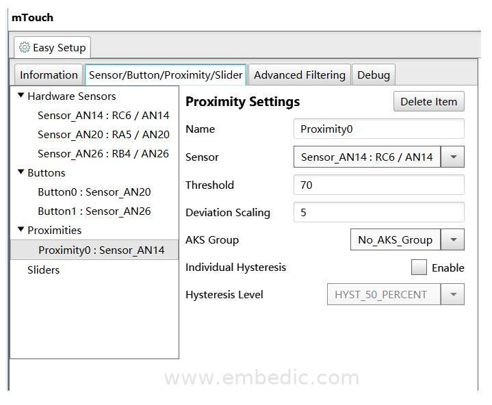
Step 6, create a new Proximity;

Step 7, Proximity and Sensor are associated;
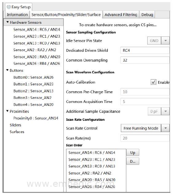
Step 8, Sensor configuration;
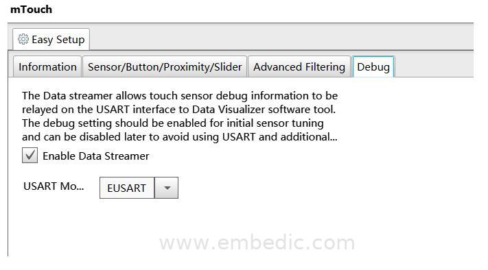
Step 9: Debug configuration and enable Data Visualizer at the same time;
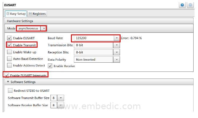
Step ten, EUSART configuration;
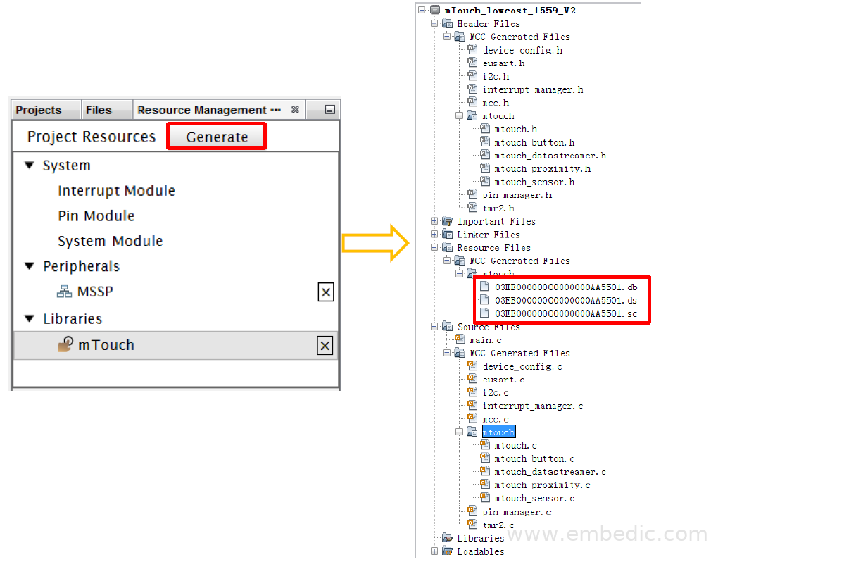
Step eleven, generate code;
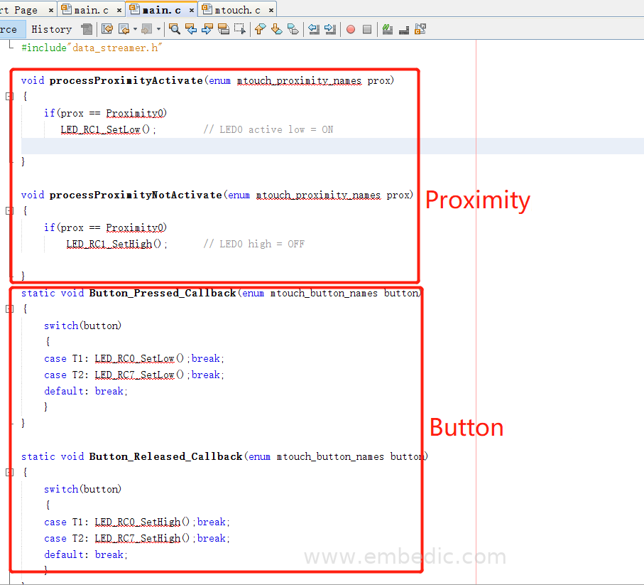
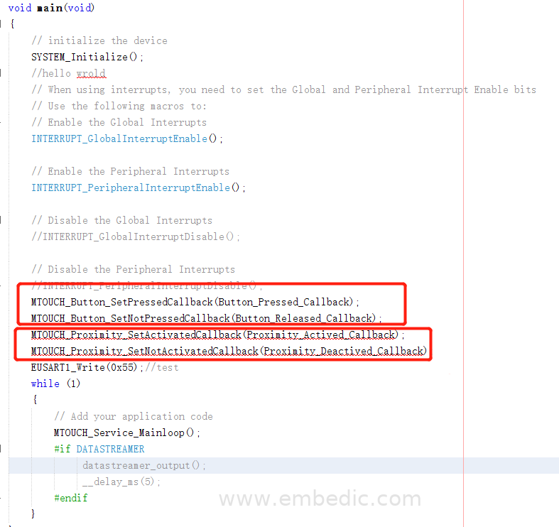
Step 12, add applications;
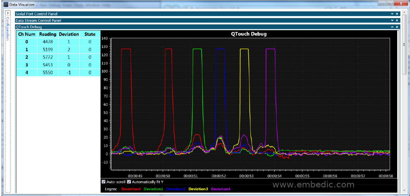
Step 13: Use the USART of Data Visualizer to debug the touch function. For details, please refer to the recorded video.
► Scenario application diagram

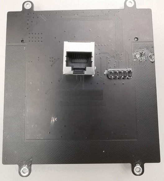
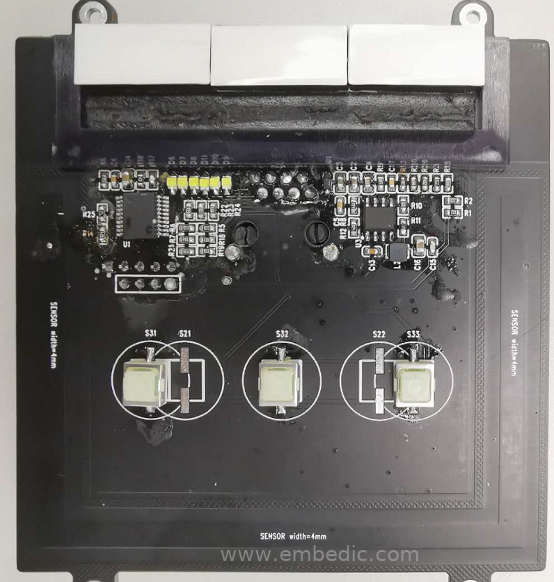
► Product entity diagram
► Showcase photos
► Core technical advantages
Microchip has the most comprehensive touch product portfolio in the industry. Products such as PIC, AVR and SAM, from 8bit MCU, 16bit MCU to 32bit MCU, all support touch-enabled MCUs and have passed automotive standard certification.
1. Pass the Q100 standard certification for automotive applications or meet Q100;
2. Free touch library, touch peripherals (ADC2 in PIC® MCU and PTC in AVR® MCU) provide high-performance touch functions and are easy to develop. Combining MPLAB IDE and MCC (code configurator) can quickly complete product design;
3. Excellent waterproof and moisture-proof touch function, anti-interference function, XLP ultra-low power consumption technology;
4. Safe touch solution with IEC/UL 60730 Class B certification Solution;
5. The system has low cost, integrates user application code, provides a full set of tools and robust touch library support, and facilitates product development.
► Solution specifications
1. Core 8bit MCU, MIPS architecture;
2. Built-in 16Mhz high-precision oscillator (±1%), maximum main frequency 32Mhz;
3. Adopt XLP ultra-low power design, standby power consumption 30na (1.8V), working power consumption 75na/Mhz (1.8V);
4, 14K Flash, 512B SRAM, 128B EEPROM;
5, 17ch * 10bit ADC, 2CH PWM, 1CH UART, 1CH I2C, 1CH SPI;
6. Up to 17ch capacitive touch channels, using mutual capacitance , Control 72 touch buttons at most;
7. Package SSOP20/QFN20/UQFN20/PDIP20;
8. Working voltage 1.8V-3.6V; 9. -40℃-85℃ or -40℃-125℃.

IC MCU 8BIT 16KB FLASH 64LQFP

IC MCU 16BIT 64KB FLASH 80TQFP
IC MCU 16BIT 8KB FLASH 32LQFP

IC MCU 8BIT 80KB FLASH 80LQFP
1
2
3
4
5
6


Product updates, events, and resources in your inbox


Smart System

Traffic Management

Security

Consumer Electronics

Wireless Technology

Robot

Internet of Things

Industrial Control