Hello! Welcome to Embedic!
Distance measurement of objects in the path of people, equipment or vehicles or moving objects is used in a large number of applications such as robotic motion control, vehicle control, canes for the blind, medical devices, etc.
There are many methods available for distance measurement, but using an ultrasonic sensor for measurement is one of the least expensive methods among other options. In this project, we will use the HC-SR04 ultrasonic sensor with an ATTIny85 microcontroller IC and an OLED display module to build a digital ultrasonic ruler.
Components needed for ultrasonic ruler
ATTIny85 IC
HC-SR04 Ultrasonic Transducer
I 2 C OLED display module
AMS1117 5V Voltage Regulator
3× 10 KΩ resistor
1× 10 µf capacitor
9V battery
Ultrasonic digital ruler circuit diagram
The schematic diagram of the ultrasonic ruler using ATTIny85 is as follows.
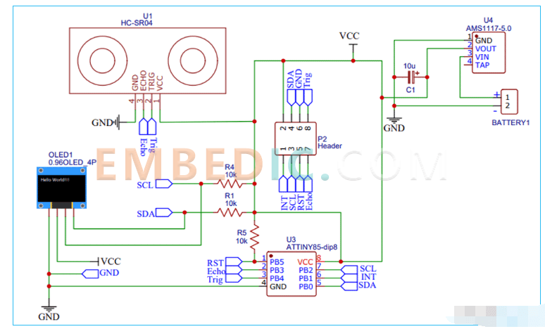
The diagram above shows the circuit diagram for interfacing the ultrasonic sensor and OLED display with the AtTIny85 IC. the interface between the OLED Display and the ATTIny85 must be implemented using the I2C protocol. Therefore, the SCL pin (PB2) of the ATtiny85 is connected to the SCL pin of the OLED Display.
Likewise, the SDA pin (PB0) of the ATtiny85 is connected to the SDA pin of the OLED display. The Echo and Trig pins of the ultrasonic sensor are connected to pins PB3 and PB4 of the ATtiny85, respectively. Finally, to power all components, we used a 9V battery. This 9V is then converted to 5V using the AMS117-5V regulator.
Note: Follow our previous tutorial to program the ATtiny85 IC directly via USB using the Digispark Bootloader or use the Arduino Programming ATtiny85 to program the ATtiny85 IC.
Ultrasonic ruler PCB fabrication
Now that we have the schematic, we can move on to laying out the PCB for the ultrasonic rangefinder using the ATtiny85. You can use any PCB software of your choice to design the PCB.
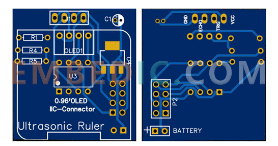
The following is a 3D model view of the top and bottom layers of the ultrasonic scale PCB.
Assembling the Attiny85 Ultrasonic Scale PCB
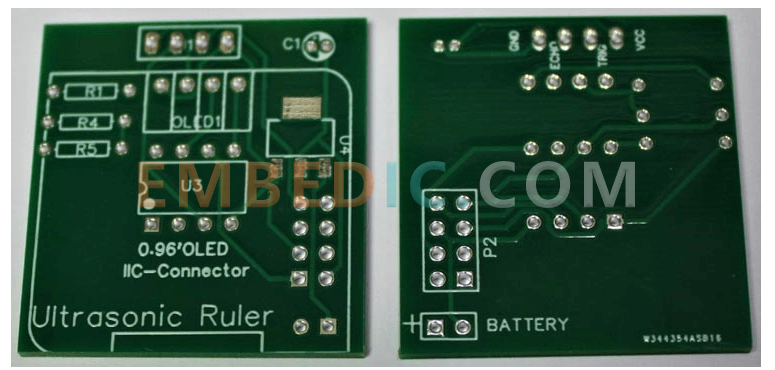
A few days later we received the PCB neatly packed and the PCB quality was as good as ever. The top and bottom layers of the board are shown below.
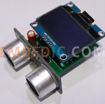
After making sure the tracks and footprints were correct. I proceeded to assemble the PCB. The fully soldered board is shown below.
ATtiny85 ultrasonic sizing instructions
The complete Arduino pedometer code is given at the end of the documentation. Here, we will explain some important parts of the code.
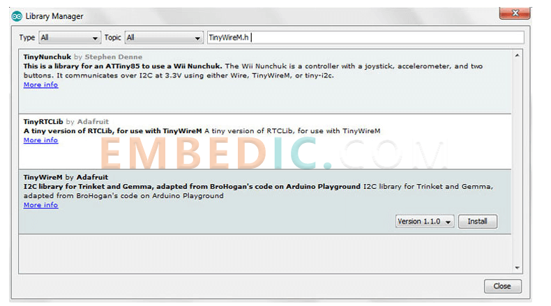
The code uses the TinyWireM.h and TinyOzOLED.h libraries. The TinyWireM library can be downloaded from the library manager in the Arduino IDE and installed from there. To do this, open the Arduino IDE and go to Sketch, Include Library, Manage Libraries. now search for TinyWireM.h and install Adafruit's TinyWireM library.
And the TinyOzOLED.h library can be downloaded from the given link.
After installing the library to the Arduino IDE, start the code by including the required library files.
#include "TinyWireM.h"
#include "TinyOzOLED.h"
In the next few lines, define the ultrasonic sensor pins. We have defined the trigger and echo pins for the ultrasonic sensor as follows.
constant int trigPin = 4; //P4
int echoPin = 3; //P3
Then comes the setup() function. This is where we define the ATtiny85 pins as inputs/outputs and start the communication between the ATtiny85 and the OLED.
Invalid setup() {
TinyWireM.begin();
ozOled.init();
OzOled.clearDisplay();
OzOled.setNormalDisplay();
OzOled.sendCommand(0xA1);
OzOled.sendCommand(0xC8);
pinMode(trigPin, output).
}
Now in the loop() function, we first measure the distance using the ultrasonic sensor and then display it on the OLED display. To measure the distance using the ultrasonic sensor, first you must set the trigger pin to the LOW state for 2 µs to ensure clarity.
Now to generate the ultrasound, set the trigPin to high for 10 µs. Afterwards, use the pulseIn() function to read the travel time and store the reading in a variable named "duration". pulseIn() has 2 parameters, the first is the name of the echo pin and the second is the state of the echo pin. The second one is the state of the echo pin. Then, after getting the distance, we display it on the OLED display.
Digital write (trigPin, low).
Delay microseconds (2).
digitalWrite(trigPin, HIGH);
Delay microsecond (10).
digitalWrite(trigPin, LOW).
pinMode (echoPin, input).
duration = pulse input (echoPin, HIGH).
cm = microseconds to centimeters (duration).
OzOled.printString("Distance:", 3, 4);
OzOled.printNumber(cm, 0, 12, 4);
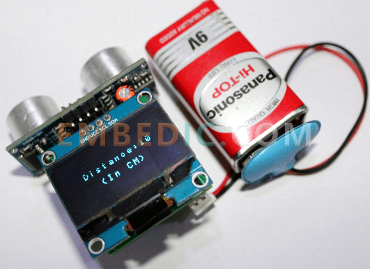
Testing our ultrasonic scales
After assembling the PCB and programming the ATtiny85 for distance measurement, we can now test the ultrasonic scale. To do this, use 9V to power the board and wait for the measured distance to be displayed on the OLED display. You can use a scale or tape measure to check if the measured distance is correct.
#include "TinyWireM.h"
#include "TinyOzOLED.h"
const int trigPin = 4; //P4
int echoPin = 3; //P3
int duration, cm.
void setup() {
TinyWireM.begin();
ozOled.init ();
OzOled.clearDisplay ();
OzOled.setNormalDisplay ();
OzOled.sendCommand (0xA1); // set direction
OzOled.sendCommand (0xC8);
pinMode (trigPin, output).
}
void loop()
{
//OzOled.clearDisplay();
digital write (trigPin, low).
Delay microseconds (2).
digitalWrite (trigPin, HIGH);
Delay microseconds (10).
digitalWrite (trigPin, LOW).
// Set the input pins with uS
pinMode (echoPin, INPUT) to receive the duration.
duration = pulse input (echoPin, high).
// Convert pulse propagation time to distance
cm = microsecondsToCentimeters (duration);
Display OLED ().
Delay (1000).
OzOled.clearDisplay ();
}
void displayOLED() {
OzOled.printString("Distance:", 3, 3);
OzOled.printNumber(cm, 0, 12, 3);
OzOled.printString("(in CM)", 5, 5);
}
long microsecondsToCentimeters (long microseconds)
{
// speed of sound is 340 m/s (29 us/cm)
return microseconds / 29 / 2;
}
IC MCU 8BIT 160KB FLASH 80LQFP

IC MCU 32BIT 128KB FLASH 100LQFP

IC MPU Q OR IQ 800MHZ 689TEBGA
1
2
3
4
5
6


Product updates, events, and resources in your inbox


Smart System

Traffic Management

Security

Consumer Electronics

Wireless Technology

Robot

Internet of Things

Industrial Control