Hello! Welcome to Embedic!
This project mainly introduces the equipment and product development of network audio live broadcast. Before developing the system, understand that audio anchors usually need the following common equipment in their work:
With the progress of society, products for creating personally exclusive internet celebrities have sprung up, and today’s most popular webcast projects have shined in various fields, among which the most popular audio webcast products in the market are all Hot competition area for big manufacturers. Let’s first popularize and understand what “webcasting” is.
It can be roughly divided into two categories. One is to provide TV signals on the Internet, such as the live broadcast of various sports games and cultural activities. ) The signal is collected and converted into a digital signal and input into the computer, and the website is uploaded for people to watch in real time. +Video) Import the director (director equipment or platform), upload it to the server via the Internet, and publish it to the website for viewing.
1. Microphone
There are two main types of microphones used by audio anchors, one is a dynamic microphone, and the other is a condenser microphone. Entertainment anchors and most non-MC (calling microphones, hosting) use condenser microphones.
2. Headphones
Generally speaking, in-ear monitor headphones and head-mounted monitor headphones are more common.
3. Microphone stand
The function of the microphone stand is to adjust the position and distance of the microphone after installation.
4. Blowout prevention net
At the beginning of the broadcast, airflow is often sprayed onto the microphone. In this way, the recorded sound will have obvious popping phenomenon, and will be accompanied by noise. Using the microphone blowout cover can effectively avoid the phenomenon of spraying the microphone. Especially when using high-sensitivity condenser microphones, installing a blowout cover can effectively avoid this phenomenon.
5. Sound card
There are two main types of sound card. The built-in sound card can connect a microphone, guitar or other musical instruments to the computer. A typical sound effect card can convert analog signals into digital audio information that the computer can process.
The sound effect card is divided into a built-in sound effect card and an external sound effect card. The desktop computer is equipped with a built-in sound card, and the built-in independent sound card will perform better than a sound card with a USB interface at the same price.
External sound card. Its built-in powerful sound effect processor integrates many functions such as reverberation effect and voice change effect, which can easily realize the use modes of Internet K song (listening to wet recording), web live broadcast, host shouting, voice chat, music listening, professional recording, etc. .
The Internet celebrity live broadcast equipment based on "Realtek RTL4040/4042 with RWS Bluetooth" can easily fulfill the above requirements of manufacturers and engineers enthusiasts who aspire to be Internet celebrity equipment.
After understanding the composition of the audio network live broadcast equipment, this article focuses on its core component, namely the core of the network audio live broadcast composed of the Realtek RTL4040/4042 chip used in this system: the smart USB sound card, which has powerful audio recording and playback functions. Meet any recording and playback function, and a package of turnkey HDK solutions allow you to easily complete the circuit design of the entire program.
1. RTL4040/4042 chip
description:
ALC4042 is a low-power single-chip USB 2.0 high-speed audio transcoder with built-in MCU for flexible use. It is suitable for earphone, earphone adapter, speaker and microphone applications. The internal MCU can also develop many different applications, such as Microsoft™Lync/Skype/VoIP devices, mobile phones or tablet PC/tablet docking devices.
ALC4042 is compatible with USB Audio Class 1.0 and USB 2.0 full speed, so it can be plug-and-play installed on the main operating system without any additional software. The internal DAC supports 44.1~384 KHz and the ADC supports 44.1~192 KHz sampling rate, with a resolution of 16/24/32 bits. ALC4042 also integrates 16K-byte OTP and crystal, but it requires few passive components to make a finished product. In this way, it can save the total BOM cost and the PCB area can be smaller.
Features:
Digital-to-analog converter with 105dBA SNR
Analog-to-digital converter with 94DBA SNR
A stereo sound DAC supports 8/16/22.05/24/32/44.1/48/96/176.4/192/384KHz sampling rate, 16/24/32 bit
Two stereo ADCs support 8/16/22.05/24/32/44.1/48/96/176.4/192/384KHz sampling rate, 16/24/32 bit
Class G headphone output, without DC blocking capacitor, ultra-low power consumption, used for headphone playback
Hardware feed-forward or feedback active noise cancellation (ANC) feature = single-ended analog microphone input with preamplifier (0/20/24/30/35/40/44/50 / 52dB)
Low noise microphone and programmable MICBIAS voltage level
Audio jack detection function
4-button headset with custom multi-function control support
An I2S digital interface, supporting master/slave working mode
A 12S digital interface support (8/16/22.05/44.1/48/88.2/96/176.4/192/384kHz, 16/24/32 bit)
I2S digital interface supports TDM format output/input
I2C control interface, support master/slave
Two stereo digital microphone interfaces
SPI (Serial Peripheral Interface, Mode 0~Mode 3) is connected to serial flash memory, used to switch codes and configure custom parameters
UART interface for connecting external devices
Built-in analog LDO
48-pin QFN'Green' package
2. RWS RTL8763BFR chip
Realtek Realtek RTL8763BFR low energy Bluetooth 5.0 dual-mode chip. This is Realtek's first TWS Bluetooth headset chip that supports AI wakeup. It is also the leader in the recent TWS 5.0 true wireless Bluetooth headset solution.
Realtek RTL8763BFR supports Bluetooth 5.0 specification, supports HFP1.7, HSP1.2, A2DP1.3, AVRCP1.6, SPP1.2 and PBAP1.0. In this system solution, RTL8763BFR is used to design a wireless Bluetooth module, which is convenient to integrate into our smart USB sound card system, so as to realize wired + wireless audio input.
The following describes the design of the Bluetooth module:
2.1, hardware design
A) Power supply design
The RTL8763BFR RWS chip supports two power inputs, a lithium battery (VBAT: 2.8-4.5V), and a power adapter that mainly charges the lithium battery (4.5V-6.5V). The charging current can reach 400mA. The chip has a built-in charging protection function.
And external environmental protection detection function, so it is very suitable for usb charging. There are two switching regulators inside the chip, respectively supplying 1.8V AVCC/AVCCDRV and 1.2V VDDCORE/VD12_SYN/VD12_RF.
B) System design
Reset circuit
In order to ensure the stability and reliability of the circuit, the RTL8763BFR RWS chip can be reset by the external reset switch triggering the HW_RST_N pin. Generally, in order to save cost and space, this solution can complete the normal reset of the system only by external charging reset (active low Low pulse> 5ms is enough).
Clock circuit
The RTL8763BFR RWS chip has two clock sources, one is that the main clock source of 40M is the normal working clock source of ARM/BT baseband, no external load capacitance is needed, and it needs to be calibrated when MP is 7~9pf. The other is RTC clock source 32.768k, which usually works in sleep mode.
Audio circuit
Audio input and output circuit design. Audio input supports three access modes (Single end mode, Capless mode, Differential mode). There are four access modes (AUX-IN, 1-MIC, Dual MIC) according to different pickups. , Digital MIC), audio output supports S /PDIF interface.
SPI Flash design
For different user needs, the RTL8763BFR RWS chip can be connected to various Flash, but try to use our recommended model (only RTL8763BM/BMR/BS):
RTL8763BF/BFR supports 8M-bits on chip FLASH memory
RTL8763BO supports 16Mbits on chip flash memory
RTL8763BM/BMR/BS support 1-bit and 2-bit mode
RF circuit design
RTL8763BO supports IQM and TPM, RTL8763BM, RTL8763BF, RTL8763BS only supports IQM
—RFIO_IQM supports dual-mode, maximum power +10dBm, receiving sensitivity -94dBm @2M EDR
-RFIO_TPM is dedicated to BLE maximum power +4dBm
Antenna design
Support pifa antenna, chip antenna, thimble antenna, specific antenna design can refer to Realtek original factory reference design and recommended manufacturers (Wancheng, Huaxinke, etc.)
Peripheral pin design
RTL8763BFR RWS chip software design adopts one-stop "dumb" design technology, allowing all customers to easily build their own RWS wireless headset system. The main software design is as follows:
A) MCU configuration
The MCU configuration tool is mainly for system control. Through the configuration tool, .SCF and .APF files can be generated. The .SCF file is the system configuration file, and the .APF file is the audio application parameter configuration file.
Its main purpose is to: Customers design and generate customized configuration files and customize any source code for operations, all of which are implemented through APP UI tools. These tools are available for customers to download through specially authorized accounts.
B) DSP configuration
The DSP configuration tool is mainly for the configuration of audio, which mainly includes the following contents:
—Sound processing: 1-mic/2-mic NR (noise reduction), AEC (acoustic echo cancellation) / AES (acoustic echo suppression), MB-AGC (multi-band automatic gain control), high-pass filter (high-pass filter) ), transmitter EQ configuration, DAC / ADC settings
-Audio A2DP/output processing: support audio processing function, MB-AGC, audio amplification, parameter EQ, sender EQ configuration, audio transfer function, mode configuration, allowing developers to arrange sound effects in any order they want.
—Wireless DSP control: Bluetooth link configuration
-Peripheral hardware control: mainly define I2S interface, analog decoding interface, etc.
—SDK development interface configuration: customized according to customer requirements can be configured into voice and audio interfaces
7. Dynamic Range (Dynamic Range): The dynamic range refers to the logarithmic value of the ratio of the maximum undistorted output power during playback of the audio system to the system noise output power in static conditions, and also refers to the maximum output image of a multimedia hard disk player. The relative ratio between the light and darkest parts. Generally, the dynamic range of audio equipment with better performance is above 100dB. Dynamic range refers to the ratio of the largest signal to the smallest signal that the device can handle.
3. TPA3131D2: 20W filterless class D stereo sound amplifier
TPA313xD2 is a high-efficiency stereo audio digital amplifier power stage for driving speakers, with a peak driving power of up to 2x42W/4Ω. The printed circuit board (PCB) of the TPA3131/32D2 dissipates heat through the bottom PowerPAD, eliminating the need for a heat sink, and can continuously provide output power in the range of 2 × 4W/8Ω (TPA3131D2) to 2 × 25W/8Ω (TPA3132D2).
The TPA313xD2 advanced oscillator/PLL circuit uses multiple switching frequency options to suppress AM interference; when combined with the master-slave mode synchronization option, multiple devices can be synchronized.
TPA313xD2 provides comprehensive protection against short-circuit, overheating, overvoltage, undervoltage and DC faults. In the case of overload, the device will report the fault condition to the processor to prevent itself from being damaged.
Features compatible devices include: 2 × 50W TPA3116D2 (PowerPAD facing up), 2 × 15W TPA3130D2 (PowerPAD facing down), and 2 × 30W TPA3118D2 (PowerPAD facing down).
Product Features
Korg Nutube 6P1 is a modern renewal product of the classic double-three-tube heat pipe valve (vacuum tube) based on vacuum fluorescent display (VFD) technology. Its size is smaller and its power consumption is much lower, but it can provide the same harmonic-rich audio as traditional vacuum tube amplifiers. It has an anode grid filament structure, which is the same as the three-yard vacuum tube. It is packaged in a convenient DIL format, and even "luminous" like the original. There is a fluorescent film on the imaging plate, which is similar to a vacuum fluorescent display. When current flows, it will produce green and white light.
Nutube 6P1 chips provide high reliability over a lifetime of up to 30,000 hours. It can operate at voltages as low as 5V and can only provide 12mW (per channel) in terms of power consumption. Nuctube 6P1 also provides excellent linearity, similar to an ideal double triangle code.
Nuctube 6P1 is the ideal device for development, prototyping and manufacturing, whether you are a Diyer or OEM organization. It can be used to create a headphone amplifier or a guitar amplifier. Small working current is also suitable for battery-powered equipment.
How big is it?
The size of the tube package is 45 x 16 x 5.6 (not including pins).
How much power does it use?
Nuctube uses less than 2% of the electricity used by traditional tubes.
Real vacuum tube sound:
The button tube produces a warm and unique vacuum tube sound. It provides excellent linearity.
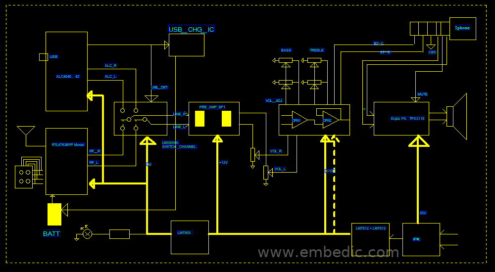
The power supply system of the whole machine is powered by a 24v external power supply. The 24v main power supply is the power supply of the subsequent PA amplifier. The direct power supply can provide sufficient power, and then the step-down output 12v->5v->3.3v LDO is used for the power supply of other internal systems. The circuit is small, flexible and simple.
Because this system uses ALC4042 as the main control of the sound card, its built-in fw eliminates the development process of general software products. If you need to customize the fw, you can modify the fw through the original factory. Here we use the RTL8763BFR module as the main control, through the flexible programming of this chip to solve some simple system workflow control, as for the software development of RTL8763BFR, this article does not give a more detailed description, readers can refer to the author’s other solutions and Manuscript.
Audio AUDIO equipment testing, mainly testing frequency response, distortion THD, signal-to-noise S/N, noise NOISE, of course some also require test power, commonly used test instruments are Audio Precesion (now), 7723A/B (early). Generate a sinusoidal signal and input it into the device, and monitor the output signal from the output.
From the measurement of key points such as microphones, power amplifiers, speakers, etc., the main technical indicators for measuring audio equipment include frequency response characteristics, harmonic distortion, signal-to-noise ratio, and dynamic range. The following briefly introduces the common test indicators of audio equipment:
1. Level: Commonly used test levels in audio equipment testing mainly include the following:
①A given output level, such as 1V, 1W or unity gain;
②A level that can produce a fixed distortion, such as 1% THD+N;
③Equipment working level, low noise and appropriate headroom at the same time;
④The input or output level specified by the test document. When testing, you should choose the appropriate level to measure the equipment according to the situation, so you must first be very clear about which level you should use. Generally speaking, according to the performance of DUT (Device under test), the gain can be adjusted to achieve the specified test level by adjusting the gain, but the DUT with fixed gain cannot be performed by adjusting the gain.
If DUT output is required For a 1Vrms signal, use AP’s Signal Generator to output a 1KHz sine signal, set the Level unit in the AP’s Analyzer window to V, and then adjust the output amplitude of the signal generator so that the Level value in the Analyzer becomes 1V; Need to test the DUT output 1W, the method to find the input level is similar, just select the unit of Level as W; of course, for the 1% THD+N input signal, you need to use the Function in the Analyzer window Reading can be selected as THD+N Ratio.
2. Frequency response (FrequencyResponse): Frequency response measurement observes the output level generated after the level of different frequencies is input to the device under test, which is an evaluation of the frequency response capability of the digital-to-analog/analog-to-digital converter in the audio equipment standard. Normally, a constant amplitude sine wave is used to scan from extremely low frequency to extremely high frequency and input to the device.
If the response of the device is very flat, then the reflection on the frequency response curve should be the output level of all frequencies, etc., and there is almost no trace. Changes and the slope is close to zero. The simplest full-band response measurement can only select the extremely low and extremely high intermediate frequencies in the frequency band to be tested for testing.
If the input levels of these frequencies are the same, the output level of the device under test represents its actual response to these frequencies. In the low-frequency and high-frequency parts, signal reconstruction is more difficult, so there is usually attenuation in these two frequency bands. The better the output quality of the device, the flatter the frequency response curve will be. On the contrary, it not only attenuates quickly at high and low frequencies, but may also exhibit jitter in general frequency bands.
3. Total Harmonic Distortion plus Noise (THD+N, Total Harmonic Distortion plus Noise): Harmonic distortion is an additional frequency signal added to the audio signal. The harmonic frequency is an integer multiple of the original signal. Total harmonic distortion is the sum of all measurement results of the harmonics of the equipment under test.
THD+N will vary according to the measurement bandwidth, so high-pass and low-pass filters are needed to limit the measurement bandwidth, and the actual bandwidth used during the test should be indicated in the result part. The commonly used bandwidth range is 20Hz to 20kHz. THD+N will also vary with the level and frequency of the applied signal. So usually use about 1kHz intermediate frequency signal and standard work or * output level to measure equipment.
4. Crosstalk (Crosstalk): In a multi-channel audio system, it usually happens that the signal of one channel leaks to another channel in the form of low level. This kind of cross-channel leakage signal is called crosstalk. Usually expressed as the ratio between the leaked signal and the original signal, crosstalk is very difficult to eliminate in actual equipment.
Crosstalk is mainly the result of capacitive coupling between device channel conductors, and it usually exhibits characteristics that increase with frequency. The crosstalk result is usually just a single number. However, the frequency sweep test of the equipment can objectively reflect its actual crosstalk performance in the working bandwidth.
To test the Crosstalk of audio equipment on the AP, usually to ensure that the two channels of the DUT have the same input impedance to the ground, the two channels of the DUT must be connected to the AP signal output ports A and B respectively. When the crosstalk of A is tested by B , Then turn off channel A in the AP signal generator, only turn on channel B, and select the Crosstalk function in the Analyzer window to select channel A, you can directly read the crosstalk size under the fixed frequency input, of course, input the sweep signal Sweep frequency test Crosstalk in the full frequency band.
5. Signal-to-noise ratio: The level of noise often depends on how big your signal is. The signal-to-noise ratio (SNR) is a specific reflection of the performance of this equipment. The input signal is usually the standard operating level of the device or the maximum undistorted output level. The signal-to-noise ratio result measured using the maximum undistorted output level is also called the dynamic range, because it describes the two extreme performance values of the device under test.
Dynamic range has a somewhat different meaning for digital devices. It is usually expressed in negative decibels. In the traditional SNR measurement method, two measurements and a few calculations are required. First control the AP (or the gain of the DUT) to find the level at which the THD+N of the DUT reaches the 1% distortion point as the reference level, set the reference level to the AP by pressing the key F4, then turn off the generator and set the reading unit SNR can be read directly for dBr. Pay special attention to the use of filters to limit the measurement bandwidth when testing SNR.
6. Phase: In the audio industry, phase measurement refers to measuring the time offset of a periodic waveform (such as a sine wave) within a cycle based on a reference waveform. The reference waveform is usually the same signal or related signals of different channels at different nodes in the system.
Equipment input/output phase and inter-channel phase are the two most common phase measurement methods. The phase shift will vary depending on the frequency, so usually multiple frequencies or sweep the frequency to get the phase response diagram.
Generally, the phase difference is not sensitive to the level, so it is enough to set the output voltage of the DUT to be higher than the background noise without distortion, and the phase difference between the channels will change with the change of the frequency, so in order to fully reflect the phase difference Information is usually swept frequency measurement.
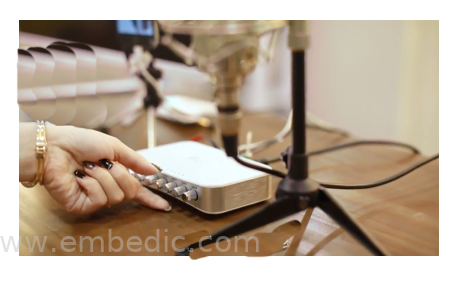
► Scenario application diagram
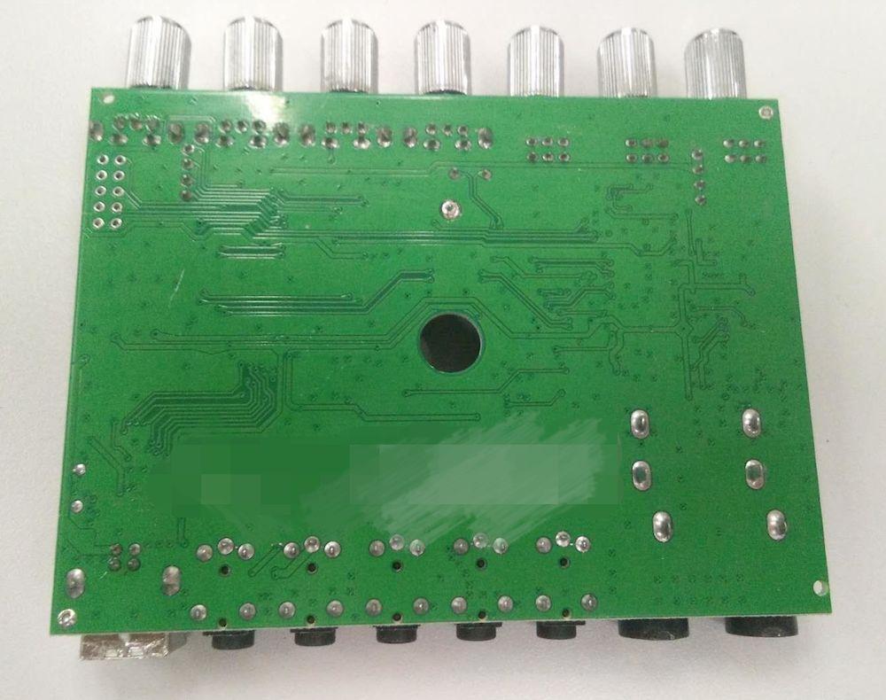
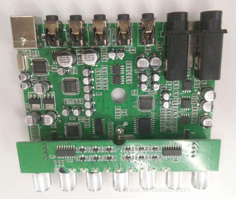
► Product entity diagram
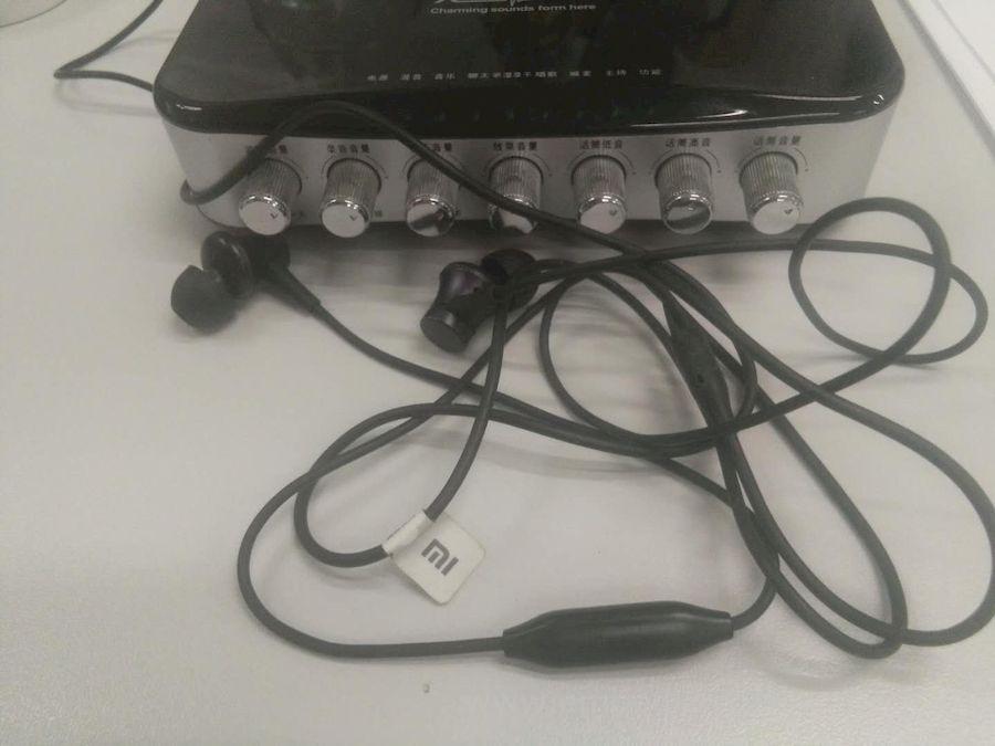
► Showcase photos
► Scheme block diagram
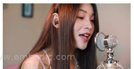
► Live scene map
► Core technical advantages
1. D/A converter with 105dBA SNR
2. Analog-to-digital converter with 94DBA SNR
3. A stereo audio DAC supports 8/16/22.05/24/32/44.1/48/96/176.4/192/384KHz sampling rate, 16/24/32 bit
4. Two stereo ADCs support 8/16/22.05/24/32/44.1/48/96/176.4/192/384KHz sampling rate, 16/24/32 bit
5. Class G headphone output, without DC blocking capacitor, ultra-low power consumption, used for headphone playback
6. Hardware feedforward or feedback active noise cancellation (ANC) feature = single-ended analog microphone input with preamplifier (0/20/24/30/35/40/44/50 / 52dB)
7. Low noise microphone and programmable MICBIAS voltage level
8. Audio jack detection function
9. 4-button headset with custom multi-function control support
10. An I2S digital interface, supporting master/slave working mode
11. A 12S digital interface support (8/16/22.05/44.1/48/88.2/96/176.4/192/384kHz, 16/24/32 bit)
12. I2S digital interface supports TDM format output/input
13. I2C control interface, support master/slave
14. Two stereo digital microphone interfaces
15. SPI (serial peripheral interface, mode 0~mode 3) is connected to serial flash memory, used to switch codes and configure custom parameters
16. UART interface for connecting external devices
17. Built-in analog LDO
18. 48-pin QFN'Green' package
► Solution specifications
Smart USB sound card with Bluetooth wireless solution
1. Main control solution: High-performance Realtek ALC4042 + RTL8763BFR Bluetooth wireless
2. Program features:
The high-performance Realtek ALC4042 has a 105dBA SNR digital-to-analog converter, which is very suitable for the field of portable audio live broadcast, with excellent sound and sound effects;
According to different requirements, it can support the function of earphone and loudspeaker;
Support multiple signal input formats and methods (wireless and wired);
Provide SDK, API and other secondary development interfaces; users can control the complete property page such as brightness, contrast, saturation, and clarity;
3. Application areas:
Portable audio player; portable audio live broadcast equipment application;

IC MCU 8BIT 8KB FLASH 20MLP

IC MCU 8BIT 80KB FLASH 52LQFP

IC MCU 16BIT 32KB FLASH 28SSOP
IC MCU 8BIT 32KB FLASH 64QFN
1
2
3
4
5
6


Product updates, events, and resources in your inbox


Smart System

Traffic Management

Security

Consumer Electronics

Wireless Technology

Robot

Internet of Things

Industrial Control