The microcontroller can be used to control the switching power supply in computer peripherals such as inkjet printers and laser printers composed of TOPSwitch FX.
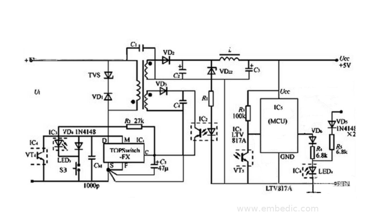
The microcontroller can be used to control the switching power supply in computer peripherals such as inkjet printers and laser printers composed of TOPSwitch FX. The circuit is shown in the figure.
Transfer files for [membrane switch] proofing
The switching power supply part is mainly composed of TOPSwitch? FX (IC1) and optocoupler (IC2). The control circuit includes a microcontroller (MCU), two LTV817A linear optocouplers (IC3, IC4), and a button switch SB. Only the signal generated when SB is pressed is valid, and the signal does not work when it is lifted. There is no need to add an anti-jitter circuit to the SB, because the soft-start time of the switching power supply (about 10ms) and the reset and initialization time of the MCU can play a delay role, which can avoid the jitter interference time when the SB is pressed; and Only when the switch is pressed for at least the above-mentioned time, can the switch power supply be turned on through the MCU. This requires that the SB must be pressed to the end, rather than lightly clicked to ensure that the power supply starts.

After MCU resets and initializes, it detects the power-on signal from IC3, and then locks the switching power supply through IC4. The LED light-emitting tube and photosensitive triode in the optocoupler IC3 and IC4 are represented by LED3 and VT3, LED4 and VT4 respectively. Now connect LED3 between the control terminal and the upper end of the SB, and connect VT3 to the logic input terminal of the MCU. Under normal conditions, no current flows through LED3 and IC3 does not work. The logic output terminal of the MCU is connected to the anode of LED4 through isolation diode VD6 and resistor R4. VT4 is connected between the M and S terminals. Because the M terminal has a current limiting function, VT4 does not need to add a current limiting resistor. CM is the denoising capacitor of the multi-function terminal.
When the user presses SB for the first time, VD4 is turned on, M terminal is connected to S pole through VD4, TOPSwitch? FX is working in three-terminal mode, multi-function terminal (M) and switching frequency setting terminal (F) do not work At this time, there is current passing through LED3, and VT3 sends a start signal to MCU.
If the switching power supply is initially in the off state (the M terminal is floating), the power is turned on when the SB is pressed for the first time, and the +5V output voltage UCC provides the working power supply voltage for the MCU. After MCU receives the start signal, it turns on VT4 to keep the switching power supply in the on state and output normally. When the user presses the SB again, a shutdown signal will be sent out. After receiving the signal, the MCU will execute the shutdown procedure and stop the print head of the inkjet printer in a safe position. Once the shutdown program is executed, the MCU cuts off VT4, suspends the M terminal, and the switching power supply enters the shutdown mode. At this time, TOPSwitch? FX is in a low power consumption state. When UI=230VAC, the chip power consumption is only 160mW. If it is used as a switching power supply in DVD, the shutdown program can also store the data and setting status in the E2PROM together, and it will not be lost even after power failure.
IC MCU 8BIT 3.5KB OTP 18SOIC
IC MCU 8/16BIT 64KB FLASH 64TQFP
IC MCU 16BIT 64KB FLASH 100TQFP
1
2
3
4
5
6