Hello! Welcome to Embedic!
The LED adaptive dimming system not only creates a comfortable environment with constant brightness, but also makes full use of natural lighting and greatly saves energy.
Compared with incandescent lamps, LEDs have a significant difference: that is, the brightness of LEDs is basically proportional to the magnitude of the forward current flowing through the LEDs.
Using this feature, the brightness of the surrounding environment is measured by the light sensor, and the luminous brightness of the LED is changed according to the measured value to achieve the effect of maintaining the brightness of the surrounding environment, and to construct a working environment that makes people feel happy.
This not only creates a comfortable environment with constant brightness, but also makes full use of natural lighting and greatly saves energy. Therefore, the research of LED adaptive dimming technology is extremely important.
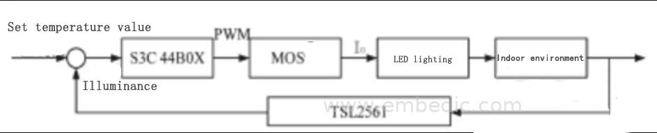
Realizing LED adaptive dimming requires real-time automatic collection of indoor ambient illuminance and feedback to the controller. The controller adjusts the PWM duty cycle according to this illuminance value, and then adjusts the voltage between the MOS gate and the source to control the positive flow through the LED.
To make the indoor environment illuminance approximately equal to the set value, and finally achieve the LED adaptive dimming. The principle of LED adaptive dimming is shown in Figure 1. The LED adaptive dimming system mainly includes four parts: controller S3C44B0X, light sensor chip TSL2561, LED dimming circuit and LED lamps.
1.1, controller chip
The S3C44B0X microprocessor is a highly cost-effective and high-performance microcontroller provided by Samsung for handheld devices.
It uses the ARM7TDMI core and has a maximum operating frequency of 66MHz. S3C44B0X is a system formed after adding some preferred peripheral devices on the basis of ARM7TDMI, which minimizes the system cost. It has a multi-master I2C bus controller and 5 PWM timers, which can meet the requirements of this design.
1.2, light sensor chip
TSL2561 is a high-speed, low-power, wide-range, programmable light intensity digital conversion chip launched by TAOS. Its structure is shown in Figure 2. A photodiode (channel 0) and an infrared-responsive photodiode (channel 1) are used in TSL2561.
This integrated circuit provides light response capability with a 20-bit dynamic range. Two integrated integral A/D converters can convert the photosensitive current into a digital output and store it in the respective registers of channel 0 and channel 1 inside the chip.
The digital output corresponds to the light intensity of each channel and can be the input of the microprocessor. TSL2561 can be directly accessed by the microcontroller through the I2C bus protocol, and the microcontroller can control the TSL2561 by reading and writing its internal 16 registers.
1.3, dimming circuit
The LED dimming circuit is shown in Figure 3. Op amps A1 and A2 are both in a deep feedback state.

It can be seen from formula (2) that if the reference voltage Vref, the sampling resistor R4, and the resistors R2 and R3 remain unchanged, the output current I0 can be kept constant.
To adjust the brightness of the LED, add another M2 to the main loop of the constant current drive, and add a high-frequency PWM signal to the grid to change the average current of the main loop.
1.4, hardware circuit design
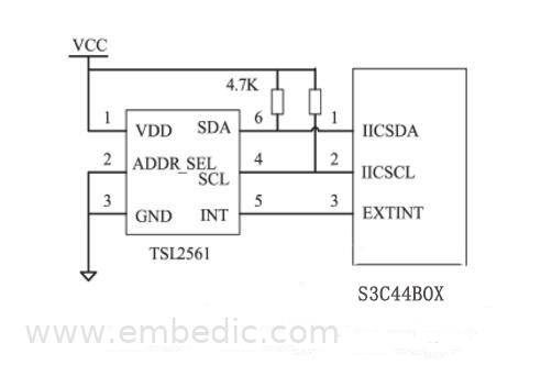
TSL2561 can be accessed through the I2C bus, so the hardware interface circuit is very simple. Since the S3C44B0X has an I2C bus controller, the clock line and data line of the bus are directly connected to the SCL and SDA of the I2C bus of TSL2561; 44B0X does not have a pull-up resistor inside, so you need to use two more pull-up resistors to connect To the bus. The hardware connection is shown in Figure 4.
2. LED adaptive dimming system software design
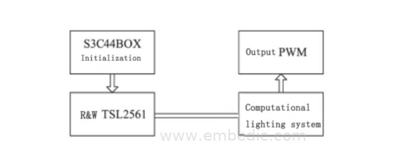
The software program design of the LED adaptive dimming system mainly includes four parts, and the design idea is shown in Figure 5.
2.1, S3C44B0X initialization and I2C read and write procedures
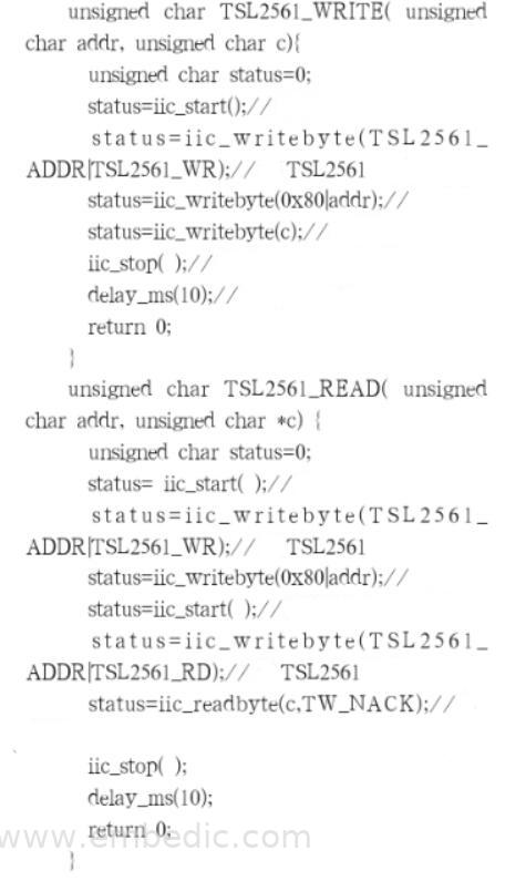
S3C44B0X has I2C bus and PWM function. If you want to use these two functions, you must first initialize the registers and I/O ports involved in these two functions. The operation of a series of registers and I/O ports involved in 44B0X will not be repeated here. Emphasize on the introduction of the subroutines TSL2561_READ() and TSL2561_WRITE() that compile and read and write TSL2561 according to the I2C standard.
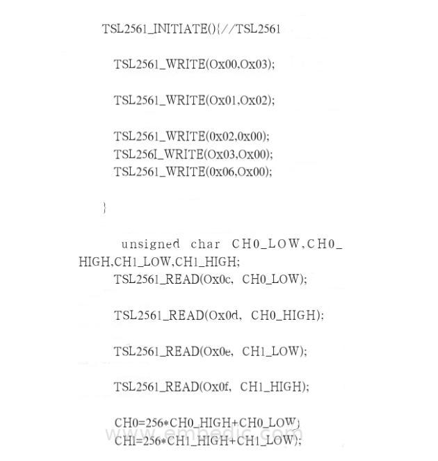
2.2. Initialization of TSL2561 and completion of data reading and writing
Before reading and writing TSL2561, first set the control word, integration time, gain and other parameter settings according to the specific system needs, and then wait for the end of the conversion to read and write the data of TSL2561.
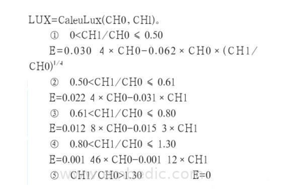
2.3, calculate the illuminance value
After reading the values of the registers of TSL2561 channel 0 and channel 1, to convert the illuminance-related values of these two channels into visible light illuminance values, certain calculations are required.
The specific conversion formula can be found in the chip's data sheet. TSL2561 has different conversion formulas for TMB and Chipscale packages. If the light intensity is expressed by E (unit is Lux), the conversion relationship of illuminance when TMB is packaged is as follows, and the conversion function LUX=CaleuLux (CH0, CHl) is designed.
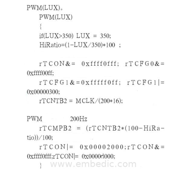
2.4, output PWM
S3C44B0X compares the indoor illuminance value with the set value, and outputs PWM signals with different duty cycles through the subroutine PWM() to adjust the LED illuminance. Assuming that the indoor illuminance is set to 350 Lux, the frequency of PWM generation is 200 Hz, and the design function is PWM (LUX).
3. Conclusion
Hardware design and software programming realize the LED adaptive dimming system to compensate for the lack of indoor illuminance and stabilize the indoor illuminance at a set level. The dimming experiment was carried out using the system, illuminance meter and LED lamps.
When the LED is not lit, measure the ambient illuminance, and then measure the ambient illuminance after adaptive dimming of the LED. In both cases, the LED and the illuminance meter are in the same position. The experimental result is that when the indoor illuminance is set to 350 Lux, the LED adaptive dimming system can basically maintain the indoor illuminance at about 300 Lux.
The system comprehensively utilizes embedded technology, sensor technology and LED dimming technology, which is of great significance for improving the performance of the LED lighting system, energy saving and environmental protection in the lighting field, and has certain practicality.
IC MCU 32BIT 64KB FLASH 81CSP
IC MCU 8BIT 16KB FLASH 64TQFP

IC MCU 8BIT 8KB FLASH 20QFN
1
2
3
4
5
6


Product updates, events, and resources in your inbox


Smart System

Traffic Management

Security

Consumer Electronics

Wireless Technology

Robot

Internet of Things

Industrial Control