Hello! Welcome to Embedic!
The LED adaptive dimming system based on single chip microcomputer is a typical green lighting method. Compared with traditional lighting, it has the advantages of intelligence, energy saving, environmental protection, long life, safety and reliability, which represents the future of lighting technology.
With the rapid economic development, the global energy consumption is growing faster and faster, and the accompanying consequences are a large number of environmental pollution and ecological destruction. Now people are looking for new energy-saving methods.
One of the more important aspects of human energy consumption is lighting. According to our country's survey, the annual electricity consumption of lighting in my country reaches more than 300 billion kWh. If all incandescent lamps are replaced by LED lighting, the energy savings will reach 100 billion kWh.
The development and application of energy-saving systems have become an urgent task. As a solid-state cold light source, LED is the fourth-generation new light source after incandescent lamps, fluorescent lamps, and high-intensity discharge lamps. The LED adaptive dimming system based on single chip microcomputer is a typical green lighting method.
Compared with traditional lighting, it has the advantages of intelligence, energy saving, environmental protection, long life, safety and reliability, which represents the future of lighting technology. Based on this, this paper designs an automatic LED light dimming system, which can automatically adjust the intensity of light according to the brightness of the environment. The system is low in cost, has strong practical significance and wide application prospects.
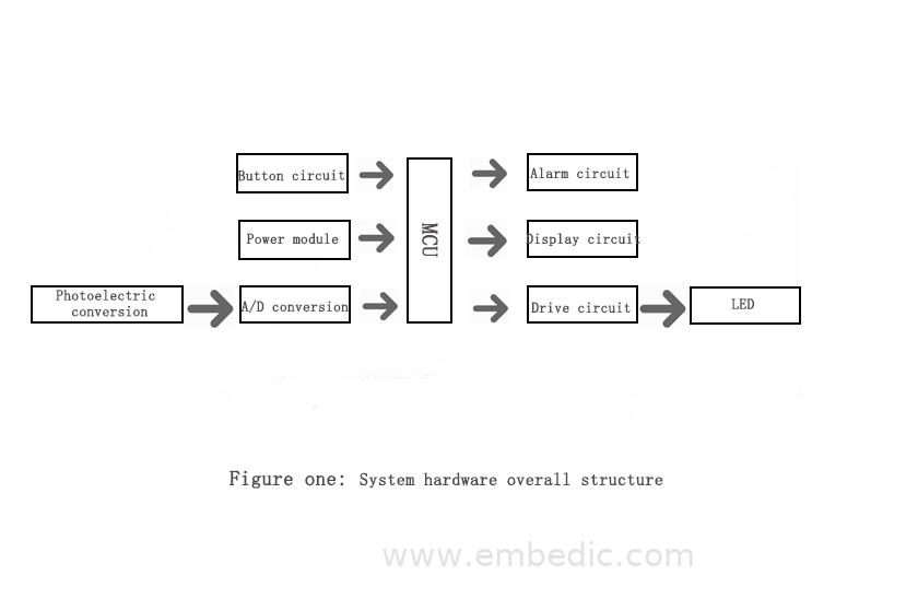
1. System hardware scheme design
The various components of the hardware system and their functions are:
1) Main control unit. The core part of the entire system device, all collected signals and data must be processed by the CPU, judged and sent out control signals.
2) Optical signal acquisition module. Real-time measurement of the ambient light intensity, and then photoelectric conversion and A/D conversion, sent to the main control unit for processing, as the target of judging light intensity information and monitoring.
3) Power module. Provide the required power supply for the device, including the digital power required by various integrated chips, the analog power required by the acquisition unit and the power supply of the LED drive circuit. The power supply must be able to ensure its stability so that each unit can work normally.
4) Button circuit. Used to set the ambient light alarm value.
5) Alarm and display circuit. The alarm circuit is used to automatically alarm when the ambient light is lower than the set ambient light alarm value. The display circuit is used to display the intensity of the ambient light.
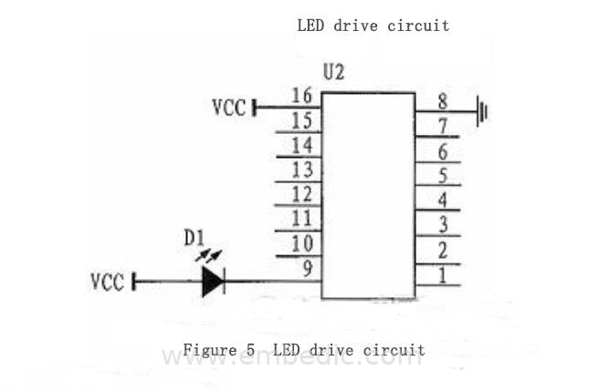
6) LED light drive circuit. The drive chip ULN2003 receives the PWM signal sent by the microcontroller to drive the LED light and adjust its brightness.
2. System design scheme
2.1. Selection of MCU
The STC12C5A60S2 single-chip microcomputer comes with up to 60K FLASHROM, and the user of this kind of process can erase and rewrite instantly with electricity. And STC series single-chip microcomputer supports serial port programming. Obviously, this kind of single-chip microcomputer has very low requirements for development equipment, and the development time is greatly shortened.
The program written into the single-chip microcomputer can be encrypted, which can protect your labor results from infringement. The important point is that the current price of STC12C5A60S2 is similar to that of the traditional 51, and the market supply is also abundant. It is a cost-effective microcontroller. Taking into account the strong representativeness of MCS-51 single-chip microcomputer and the large number of materials of this series of single-chip microcomputers, this design adopts STC12C5A60S2 single-chip microcomputer to realize.
2.2, LED light dimming scheme
Use pulse width modulation (PWM) for dimming. Adjust the driver chip by PWM wave generated by STC12C5A60S2 to achieve the purpose of dimming. PWM dimming has the characteristics of high precision, energy saving, and easy realization of intelligent control.
This system intends to use STC12C5A60S2 single-chip microcomputer as the main control module. The photoelectric conversion circuit collects the external light intensity signal and sends it to the single-chip microcomputer for processing through A/D conversion. The single-chip intelligently adjusts the output PWM according to the processing result to control the current of the drive circuit. Adjust the brightness of the LED.
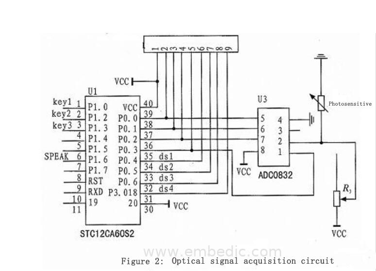
2.3. Optical signal acquisition circuit
The light detection circuit is a more important part, among which there are two key components, one is a photosensitive resistor and one is an adjustable resistor. The photoresistor changes its resistance by the current intensity of the ambient light, thereby changing the voltage at both ends of it to achieve the effect of controlling the brightness of the LED light.
You can also add an adjustable resistor according to the actual situation, by changing the size of the resistor To change the sensitivity of the photoresistor. If you think that the sky is still bright, turn on the light, then increase the resistance, and the sensitivity of the photoresistor will decrease, so that you can wait until the sky is dark before turning on the light.
Similarly, the sky is already very dark. If the light is not on, then adjust the resistance to a small value, so that you can adjust the LED light to the most ideal and suitable state by repeating the adjustment several times. The figure below shows the optical signal acquisition circuit.
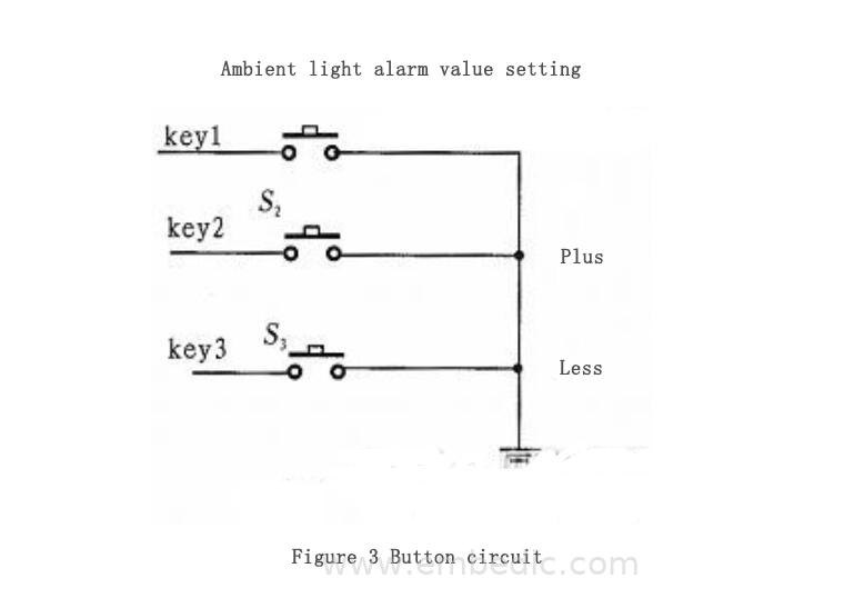
2.4 Design of button circuit and alarm circuit
A stand-alone keyboard is a key corresponding to a port input, and each key has a key circuit to distinguish whether a key is pressed. These buttons can be directly connected with the I/O line of the single-chip microcomputer or connected with the data line through the input port, and the structure is relatively simple. The button circuit is shown as in Fig. 3.
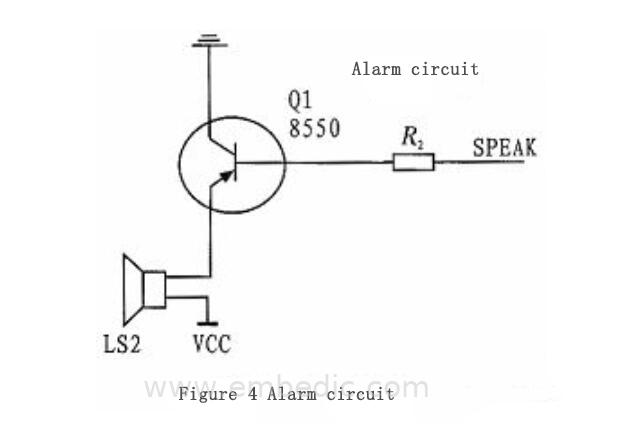
When the ambient light is lower than the set ambient light alarm value, it will automatically alarm. Figure 4 shows the alarm circuit.
2.5, LED drive circuit design
The light drive circuit is the key to the hardware circuit in the whole system. It determines the working performance of the whole system, and the system uses PWM control automatic dimming to realize indoor brightness adjustment.
ULN2003 is a high-current drive array suitable for control circuits such as single-chip microcomputers, smart meters, PLCs, and digital output cards. These loads can be directly driven by the relay.
When the input is 5VTTL level, the output can reach 500mA/50V. ULN2003 is a high withstand voltage, high current Darlington display, composed of seven silicon NPN Darlington tubes. Each pair of Darlingtons in ULN2003 are connected in series with a 2.7K base resistor.
When working at a voltage of 5V, it can be directly connected to TTL and CMOS circuits, and can directly deal with the original standard logic buffers. ULN2003 is a product of Darlington transistor array series with high voltage and high current. ULN2003 is not only good in current gain and working voltage.
Moreover, it has the characteristics of wide temperature range and strong load capacity, which can be applied to various systems that require high-speed and high-power drive.
The output of ULN2003 can reach 500mA/50V. The scientific name of the diode at the output is a freewheeling diode. If the input terminal of the Darlington tube of ULN2003 inputs a low level to make it cut off, and the driving component is an inductive component, the current cannot be changed suddenly, and a high voltage will be generated at this time; if there is no diode, the Darlington tube will be broken down.
So this diode mainly plays a protective role. Since ULN2003 is an open-collector output, in order to make this diode play a freewheeling effect, the COM pin (pin9) must be connected to the power supply of the load, only in this way can a freewheeling loop be formed.
Because ULN2003 is needed to drive the lamp in this design, Figure 5 is the drive circuit of the LED lamp.
2.6, power module hardware design
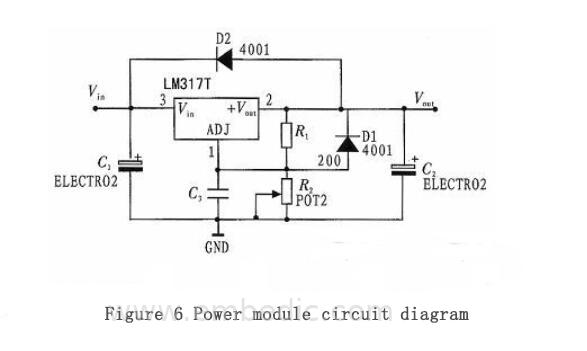
As the most commonly used by residents in my country is 220V, 50Hz AC, and the system requires +5V DC, the power module adopts a 220V to 12V transformer, then it is processed by bridge rectifier and LM317 voltage regulator chip, and finally filtered to output +5V DC voltage. The power module circuit diagram is shown as in Fig. 6.
3. Conclusion
The main advantage of this system is that the system has comprehensive functions and meets the requirements of intelligent energy saving. The technical difficulty lies in the collection of light intensity signals and the control of corresponding light intensity.
Since we use a photoresistor, the voltage across the AD collected photoresistor will be reduced by the increase in light intensity, so that the corresponding light intensity can be adjusted by mapping to the PWM duty cycle through a certain proportional relationship.
The main design source of this system comes from life, so the innovation is also to deal with some of the more common problems in life. The photoresistor collects the signal and uses the single-chip microcomputer to process it to achieve the purpose of easy control.
When the room is not bright enough, the lamp will automatically light up, eliminating the trouble of touching switches in the dark. The design is simple in structure and has strong practical significance.

IC MCU 8BIT 4KB FLASH 16DIP

IC MCU 16BIT 88KB FLASH 80TQFP

IC MCU 8BIT 1.5KB FLASH 20QFN

IC MCU 8BIT 8KB FLASH 20DIP
1
2
3
4
5
6


Product updates, events, and resources in your inbox


Smart System

Traffic Management

Security

Consumer Electronics

Wireless Technology

Robot

Internet of Things

Industrial Control