Hello! Welcome to Embedic!
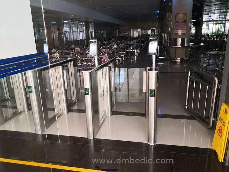
With the resumption of work in various places, office buildings, parks and other workplaces often line up for temperature measurement. How to not only complete body temperature screening, but also reduce the impact on people's normal work and life, and avoid the risk of virus transmission caused by queuing for temperature measurement, has become an important need in the process of resuming work in the society.
Faced with the sudden epidemic, all walks of life are working hard to use their profession to help fight the "epidemic". Temperature measurement and personnel tracking are important means of preventing and controlling the epidemic. With the resumption of work in various places, office buildings, parks and other workplaces often line up for temperature measurement. How to not only complete body temperature screening, but also reduce the impact on people's normal work and life, and avoid the risk of virus transmission caused by queuing for temperature measurement, has become an important need in the process of resuming work in society.
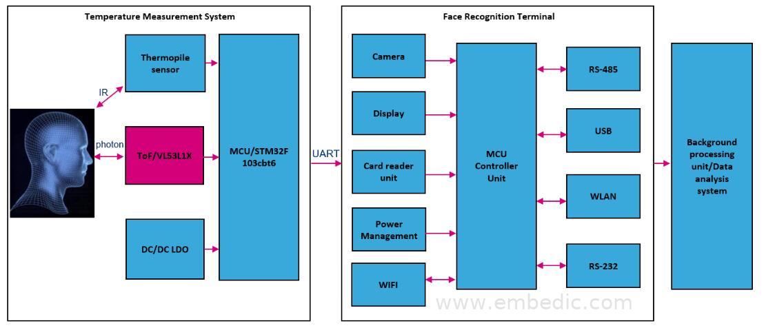
ST ToF VL53L1X product assists the face access control temperature measurement system. The main purpose of this solution ToF is to report the distance between the measured face and the thermopile sensor, so that the algorithm can compensate for the attenuation of the thermopile sensor accuracy, which can greatly increase the body temperature Measurement accuracy. Although the ToF code can return not only the distance data, but also the amount of photons returned and the ambient light interference, for most product applications, ToF measurement distance is required, and this solution also requires ToF Based on the distance measurement data, an algorithm is used to compensate the temperature according to the distance of the measured face. The temperature detection generally has a certain attenuation. Only through the support of the algorithm can the accuracy of the product be guaranteed.
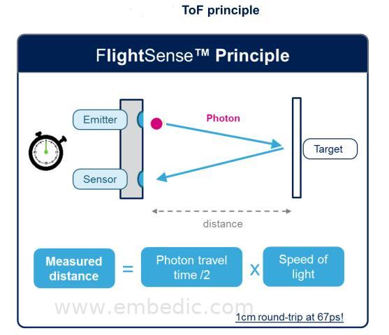
This program mainly introduces the application of ToF VL53L1X products. Below we will briefly introduce the principle technology and code flow of ToF.
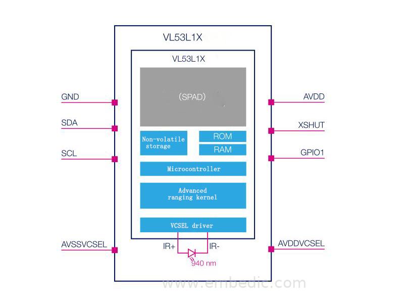
VL53L1X is the third-generation laser ranging sensor based on STMicroelectronics’ patented FlightSense™ technology. It is the most advanced time-of-flight (ToF) laser ranging sensor. It enriches ST’s FlightSense™ product series and can be used in challenging operating environments. Provides the best ranging performance even if the sensor is deployed behind a dark protective cover. It contains a SPAD (Single Photon Avalanche Diode) sensor array, an integrated 940nm invisible light source based on a first-level safety VCSEL (Vertical Cavity Surface Emitting Laser) of the human body, and a low-power embedded microcontroller. The SPAD array of this new generation sensor integrates a lens that can measure distances up to 4 meters, providing the best ranging performance in challenging operating environments, even if the sensor is deployed behind a dark protective cover.
Module system block diagram:
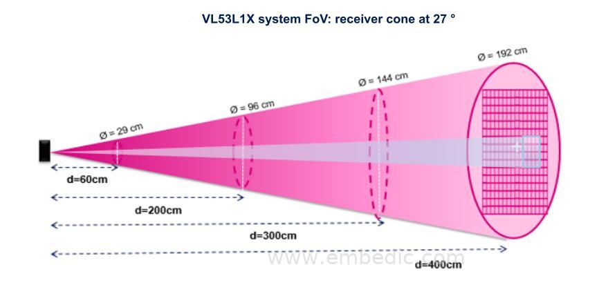
Unlike traditional IR sensors, VL53L1X uses ST's proprietary FlightSense™ technology to ensure absolute distance measurement at any target color and reflectivity. It can also reduce the sensor field of view (FoV) by programming the size and location of the region of interest (ROI) on the receiving array. The receiver sensor array of the VL53L1X device is composed of 16x16 SPADs (single photon avalanche diodes), and the full diagonal field of view FoV is 27°. Users can choose by themselves through software, but the smallest ROI configuration is 4x4 SPADs. In general application scenarios, if it is not because of obstacles that interfere with FoV and the measured object, customers are not recommended to change the FoV, because reducing FoV will affect the ToF ranging performance. For example, use a 17% gray card as the measured object and set 4x4 SPADs , That can only measure a distance of about 45cm.
Receiving array region of interest (ROI):
Adjust FoV related code reference:

Below we analyze the entire ranging process of ToF combined with the code. First, let's take a look at the overall ranging process block diagram:

One: Wait for the device boot to be ready, the function of VL53L1_WaitDeviceBooted() is to ensure that the device has been started and is ready;
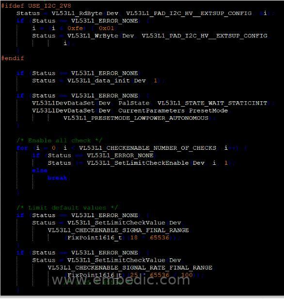
Two: DataInit, call the VL53L1_DataInit() function, in this function can be configured according to the design circuit and application requirements:
For example: the default IOVDD power supply voltage is 1.8v, if you use the 2.8v power supply mode, you need to select the 2V8 power mode code part here; also set the thresholds of VL53L1_CHECKENABLE_SIGNAL_RATE_FINAL_RANGE and VL53L1_CHECKENABLE_SIGMA_FINAL_RANGE, SIGNAL is the minimum number of photons to calculate the distance value Quantity, the unit is MCps; SIGMA is the estimate of the standard deviation of the measurement result, the unit is mm. If SIGNAL or SIGMA exceeds the limit, the ranging is marked as invalid.
Three: StaticInit, load device settings;
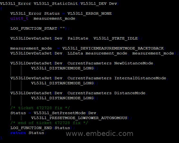
Four: Set the distance measurement mode, call VL53L1_SetDistanceMode function, there are three modes can be configured, short distance, medium distance and long distance, users can choose the corresponding mode according to different applications. The distance measurement capability of Short mode is about 130cm, the distance measurement capability of Medium mode is about 300cm, and that of long mode is about 400. The long mode is set here.

Five: Timing Budget setting, call function VL53L1_SetMeasurementTimingBudgetMicroSeconds. Timing Budget is the time allocated for the user to perform a range measurement. Generally speaking, Timing Budget sets a longer point, the more accurate the measurement data.

Six: Inter measurement budge setting, inter measurement is the delay between two ranging operations. The minimum inter-measurement value must be greater than Timing Budget + 4 milliseconds. If this condition is not met, the VL53L1_StartMeasurment function will return an error code (VL53L1_ERROR_INVALID_PARAMS).

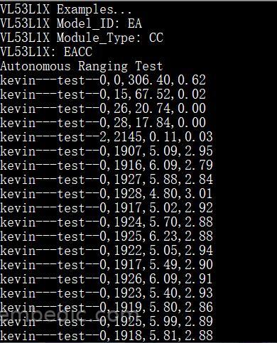
Seven: Call the VL53L1_StartMeasurement() function to start the measurement. The measurement modes include polling and interruption modes. As can be seen from the code, the printed data includes: RangeStatus, RangeMilliMeter, SignalRateRtnMegaCps, AmbientRateRtnMegaCps. RangeStatus means the status of the current data, and judge the validity of the measured data according to the return value, and other FAIL items; RangeMilliMeter represents millimeter-level measurement data; SignalRateRtnMegaCps represents the number of photons returned; AmbientRateRtnMegaCps represents photons interfered by ambient light Volume data.
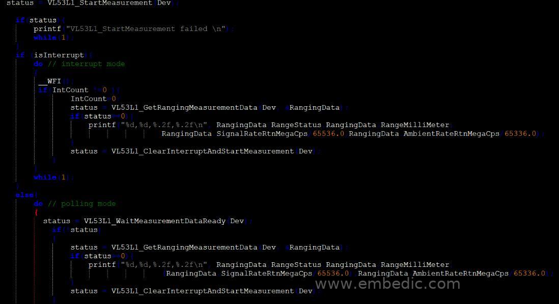
Eight: The following are the four groups of RangeStatus, RangeMilliMeter, SignalRateRtnMegaCps, AmbientRateRtnMegaCps information printed out by the serial port:
In addition, it should be noted that although each chip ST has been calibrated when it leaves the factory, because we have added protective covers during application and some interference caused by welding on the production line, if the accuracy of the measurement is If there are certain requirements, we need to calibrate the whole product before leaving the factory, including calibration of RefSPAD, offset and crosstalk;
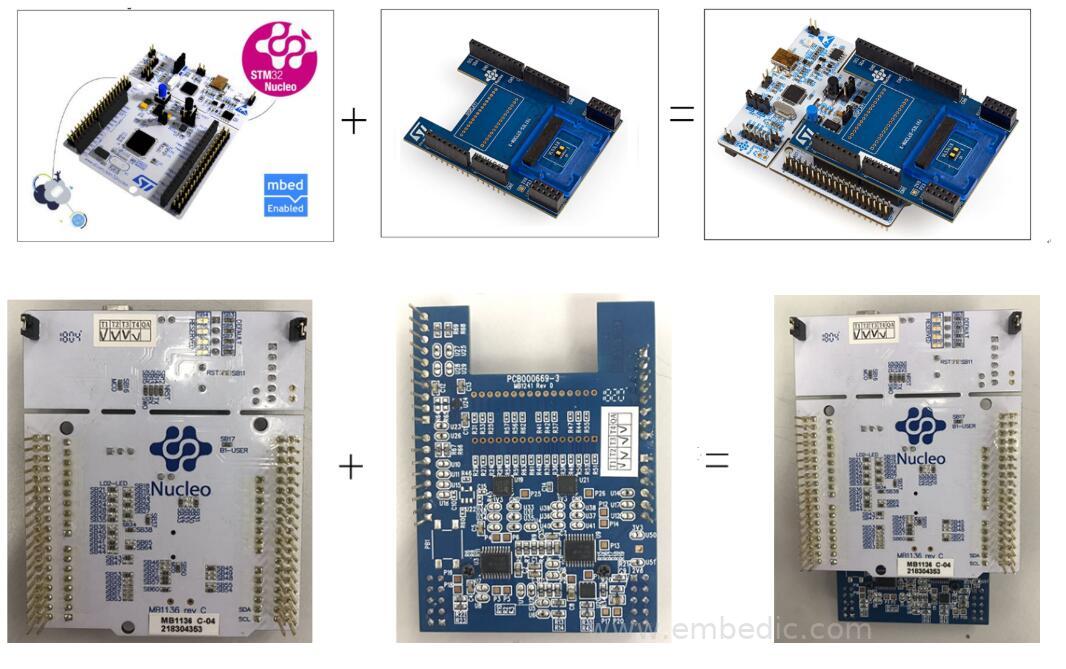
For presence detection, the automatic low power consumption mode can be activated based on threshold and interrupt settings. It can be adjusted to save system power consumption and automatically shut down or wake up the host when a person or object is detected. VL53L1X has a complete documentation package, such as source code and software API (application programming interface), and it is compatible with a range of microcontrollers and processors. X-NUCLEO expansion board, satellite board and related development ecosystem make application software development and system integration very easy.
► Scenario application diagram
► Product entity diagram

► Showcase photos
► Scheme block diagram
► Schematic diagram of ToF technology principle
► Core technical advantages
1. Long distance: absolute distance measurement up to 400cm
2. Fast: support 100 Hz ranging frequency
3. High-precision ranging
4. User detection: achieved with 1.5mW
5. Fully integrated miniaturized module: 4.9 x 2.5x 1.56 mm
6. The sensor can be deployed behind the protective cover sheet
7. The size of the region of interest (ROI) on the receiving array is programmable, and the field of view (FoV) is adjustable
8. The position of the region of interest (ROI) on the receiving array is programmable, and multi-region operation control can be performed from the host
9. Modular design, easy to integrate
► Solution specifications
1. Typical full field of view (FoV): 27 °
2. Emitter: 940 nm invisible laser (class 1)
3. SPAD (Single Photon Avalanche Diode) receiving array with integrated lens
4. Low-power microcontrollers running advanced digital firmware
5. The pinout is compatible with VL53L0X FlightSense™ ranging sensor
6. Single reflow soldering components
7. Single power supply (2v8)
8. I²C interface (up to 400 kHz)
9. Stop and interrupt pins
IC MCU 32BIT 32KB FLASH 64TQFP
IC MCU 8/16BIT 64KB FLASH 44TQFP

IC MCU 8BIT 16KB FLASH 24SOIC

IC MCU 32BIT 256KB FLASH 100BGA
1
2
3
4
5
6


Product updates, events, and resources in your inbox


Smart System

Traffic Management

Security

Consumer Electronics

Wireless Technology

Robot

Internet of Things

Industrial Control