Hello! Welcome to Embedic!
The remote control is one of the essential electronic products in every family. Therefore, it is very necessary to develop a new type of universal remote control, which can be compatible with all electrical control protocols, so that users do not have to worry about the inconsistency between electrical appliances. Compatibility issues, the new universal remote control has gradually become the leader of all household appliances!
This project is based on the new application of Realtek Semiconductor RTL8723DS. The RTL8723DS series of products are a single-chip Bluetooth/WIFI wireless chip. Their emergence has ended the past market pattern of princes' melee, and therefore has become a killer product to end the traditional remote control. Known as the contemporary "remote control killer". This project is a small and inexpensive remote smart phone application that can be controlled by multiple devices. It allows users to control appliances from anywhere in the home that can access the Internet through a smart phone. It is suitable for all types and brands of infrared control appliances to retain codes and self-learning. In addition, it has a voice recognition function. The following is a detailed introduction that is different from the traditional remote control. This is the direction of real smart home application development.
Features:
1. Only one can replace all traditional remote controls. Your smartphone will become the controller appliance for everyone
2. Even if you are at home, control the household appliances to leave the house. When you are in the office, you can use your smartphone to schedule pre-recorded playback on the TV at home a few miles away.
3. Help your family to manage your house appliances, no matter where you are. When you are traveling and your parents or children have trouble using high-tech equipment at home, you can help them operate your smartphone from the following locations.
1. Hardware
Our project is to build a smart remote control center that can connect and control traditional household appliances and new smart devices. To build this cool product, we must attach great importance to hardware circuit design, which is one of the most important parts of the hardware design in the entire development process. Hardware circuit design is divided into several key processes, including top-level design, selecting appropriate electronic components, designing electronic circuits and test programs.
1.1 System structure
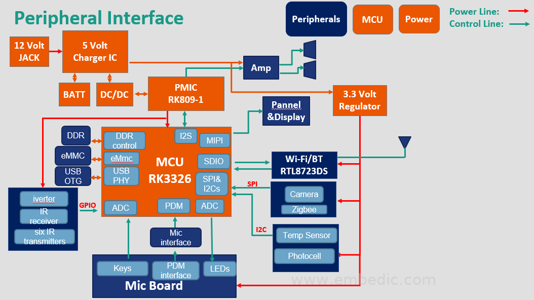
To create this smart remote control, we first need to build a hardware system to complete the function. The microprocessor is the core of the entire platform, it is the processing part necessary for all processing. The remote control contains a Wi-Fi/BT module, which is connected to the home wireless router, so it can be accessed via a mobile app. The controller also contains six infrared transmitters and one infrared receiver, so you can learn the control signal control of the traditional remote control, and then work instead. In addition, the device also contains two sensors for temperature and illuminance. In addition, a voltage regulator is required to generate a stable 3.3v power output. The following is a simplified structure diagram of the system.
1.2 Selection of main control chip
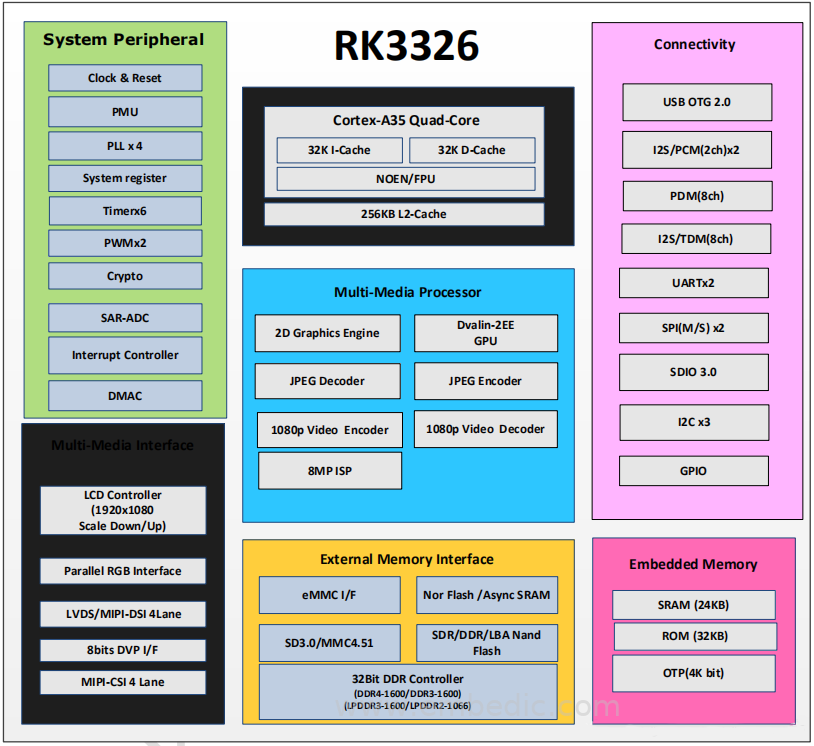
After defining the system structure, we need to find a suitable main control chip and Wi-Fi/BT chip or module. Since we are building a product that can sustainably have a long life cycle in the future, we need to consider several key criteria when making a choice, including performance, quality, price and ease of development. As shown in the picture above, we use Rockchip RK3266 and Realtek wifi/BT Combo wireless chip RTL8723DS as our core microprocessor and Wi-Fi/BT communication chip or module. The main reason we finally chose this chipset is that it perfectly balances price and performance. The chipset is not only powerful, but also a perfect combination of Wi-Fi/BT modules (in accordance with IEEE 802.11n), so it reduces the complexity of the system and solves the work of 2.4GHz RF signal transmission. As a result, fewer devices are used to implement external components required for 2.4G Wi-Fi/BT applications. Since our MCU adopts high-performance RK3266, it is a high-performance quad-core application processor designed for personal tablet computers and smart audio equipment. Provides many embedded powerful hardware engines to optimize the performance of high-end applications. RK3326 supports almost all formats of H.264 decoder, supports 1080 p@60 fps, H.265 decoder supports 1080 p@60 fps, supports H.264 encoder through 1080 p@30 fps, high-quality JPEG encoder /decoder. The embedded 3D GPU makes RK 3326 fully compatible with OpenGL ES 1.1/2.0/3.2, DirectX 11 FL9_3, OpenCL 2.0 and Vulkan 1.0. The special 2D hardware engine will maximize the display performance and provide smooth operation. RK3326 has a high-performance external memory interface (DDR 3/DDR3L/DDR 4/LPDDR 2/LPDDR 3), which can maintain the required memory bandwidth. The choice of this chip can far satisfy the future expansion of our system and the addition of flexible new functions. The following chart shows the basic block diagram:
Therefore, we can run customized Linux on it, which simplifies the advanced development of applications such as Wi-Fi/BT data processing, and avoids possible overload problems. The embedded Linux system also greatly increases the functionality and scalability of our equipment. Another reason we chose the RK3266 chipset is that it provides a variety of hardware interfaces, such as SPI, I2C and USB. These interfaces can be used to connect loads of peripheral devices and will therefore support more applications. During the system period, we found that the information on the Internet and the combination of 23ds chips that were approved were less. So the entire development process becomes quite challenging.
1.3.1 wifi/BT chip or module (RTL8723DS)
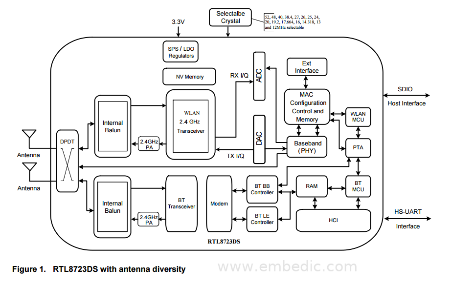
The following figure is the system block diagram of Realtek's RTL8723DS. The SDIO/UART hardware interface and GPIO external interface of RTL8723DS are used for external control. So we connect all available GPIO ports, SDIO ports and other ports in the schematic design. The internal serial transmission and reception ports TXD and RXD have been connected to test the firmware upgrade function. The chip is powered by a 3.3V DC power supply and can be reset by setting the RST port to high level. The following is the functional block diagram of the RTL8723DS SoC provided in the official data sheet:
1) Key points for attention when using RTL8723DS:
a.RTL8723DS module PIN38 supports two power supply modes, 3.3V direct power supply mode and Vbat (3.3V-5.5V) power supply mode, which need to be used strictly according to customer design. The Vbat power supply mode must be turned on and off through the Module's PIN39 (VBAT_EN). The VBAT LDO outputs 3.3V. If the original 8723DS module's PIN39 (CHIP_EN) is not pulled out, you need to use R6 and R7 on the module to divide the voltage , To enable VBAT Enable, compared to a platform where VBAT_IN cannot be off, it will save more power if it can be controlled by VBAT_EN
b. The RTL8723DS/RTL8703CS module has PIN39 (VBAT_EN) pulled out,
*For 3.3V power supply mode, VBAT_EN cannot reset the entire IC. You need to pull WL_DIS# and BT_DIS# low at the same time to reset the entire IC;
*For the Vbat power supply mode, the Vbat LDO output can be turned off, which is equivalent to powering off the IC to reset the entire IC.
* Again, when using Vbat power supply, VBAT_EN must be controlled by an external host GPIO
c. The voltage range of VBAT_EN of RTL8723DS/RTL8703CS module is 1.6V~3.3V, as long as it is within this range, VBAT will output 3.3V; Pin12(WL_DIS#)Pin34(BT_DIS#) of the same module can Support 1.8V and 3.3V, as long as it is between 1.6V~3.3V, it can be regarded as high
d. The voltage of PIN13 of the RTL8723DS/RTL8703CS Module is also determined by the PIN22 (VDDIO) of the Module, which can support 1.8V and 3.3V
e. The voltage of PIN7 of the RTL8723DS/RTL8703CS Module is determined by the PIN22 (VDDIO) of the Module, which can support 1.8V and 3.3V. But another thing to note is that this pin is also our IC TEST_MOD_SEL pin, which needs to be pulled low when the IC is powered on. There is a pull low resistance inside our IC, so we need to confirm whether there is a pull high resistance on the external host terminal, and if so, take the resistance. , Also need
Make sure that the Host side is low when our WIFI is on!
1.3.2 System Timer
In this project, a precise timer was required to generate a 38 kHz carrier infrared signal. You can also use the TLC555 timer chip provided by Texas Instruments (TI). The reason why we choose an external TLC555 as the timer chip is that it provides three operating modes: monostable mode, non-stable mode and bistable mode (Schmitt trigger), so different functions can be realized. For example, PWM or LED blinking. All these modes are easy to implement. The timer chip can run at a maximum frequency of 2 MHz, so it can handle the frequency required for infrared transmission. TLC555 supports on/off modulation mechanism on its output waveform. The RESET port determines the on/off of the timer output, so that we can modulate data by connecting this port to the GPIO port of the MCU. The trigger level is approximately one-third of the supply voltage and the threshold level is approximately two-thirds of the supply voltage. For the application circuit, we use the official Astable mode of operation including the data sheet of sequential components R7, R8 and C5. The diode D1 is used to reduce the duty cycle of the output waveform so that the power consumption can be restricted to a minimum. After testing, the oscillation can be output close to 38 kHz, so the IR LED emits pulsed IR rays at this frequency, and the output period is close to 1:3, thereby reducing power consumption by three times.
1.3.3 Infrared transmitter
In this project, the generated infrared signal is sent out by multiple infrared LEDs for remote control of household appliances. Here, we use TSAL7600 high-power infrared light-emitting diode manufactured by Vishay Semiconductors. The reason why we choose this infrared LED is its high reliability and high radiation intensity. The half-intensity angle of this IR LED is about ±30 degrees, so we decided to use 6 of this IR LED to cover all directions. From the system design point of view, the on/off of these IR LEDs will be controlled by the TLC555 timer output. According to the data sheet, the typical forward voltage of TSAL7600 LED is 1.35V. The forward current is 100mA. Therefore, it is difficult to continuously support two LED timers with a power of 5V. The output voltage can reach as high as 3V. So we decided to connect these parallel IR LEDs. Each IR LED is connected to a bipolar transistor and a small resistor. The transistor acts as a switch, and the small resistor provides enough current for the infrared LED (the maximum constant current is 150mA in the actual test). The transistor we use is a 2N2222 BJT, which can drive up to 1A.
1.3.4 Infrared receiver
In this project, an infrared receiver is needed to receive the 38 KHz infrared signal transmitted from the traditional remote control. Here, we use TSOP39338 infrared receiver module manufactured by Vishay Semiconductors. It is a small receiver specially designed for infrared rays, a remote control system in which a PIN diode and a preamplifier are assembled on a lead frame. The demodulated output signal can be directly decoded by the microprocessor, which is the main reason why we choose this infrared receiver module. Refer to the data manual for the application circuit design of this module.
1.3.5 Analog-to-digital conversion
In this project, an analog-to-digital converter is needed to convert the sensor into a digital signal, which can then be read and processed by the MCU. Here we use ADS1015 ultra-small, low-power, 12-bit analog-to-digital converter, by Texas Instruments (TI). We chose this chip as the ADC because it has four input channels, so we may integrate other sensors into the system in the future without changing the ADC chip. ADS1015 uses a serial interface compatible with I2C to transmit data, and this interface is also supported by RK3266 SoC. Compared with the SPI interface, I2C only uses two wires and is easy to implement. This interface is very suitable for low frequency data transmission, such as sensor data. Please refer to the datasheet for application circuit design.
1.3.6 Sensor
1.3.6.1 Temperature sensor
In this project, a temperature sensor is used to collect ambient temperature data. The temperature sensor we use here is LM35, this precision temperature sensor in degrees Celsius is manufactured by Texas Instruments (TI). The reason we choose LM35 as the temperature sensor is that no external calibration is required in practical applications. Another reason is accuracy: the typical accuracy at room temperature is ±0.25°C, and it covers the entire detection range of -40°C to +110°C. Please refer to the datasheet for application circuit design.
1.3.6.2 Illuminance Sensor
In this project, the lighting sensor is used to collect ambient light intensity data. The illumination sensor we use here is PDV-P1803, and the CdS photoconductor is designed by Advanced Photonix Inc. It can sense light from 400 to 700nm. It depends on the resistance of the lighting resistance in the range of 16kΩ to 33kΩ. Application Circuit Design For information about this sensor, please refer to the datasheet.
1.4 Hardware driver
To remotely control all infrared devices, the key is to understand the basic infrared protocol. We have implemented a common protocol in the driver, namely NEC infrared protocol. Even if the radio waves learned from the receiver do not belong to these two, we still have a mechanism to record and send the learning from the device.
1.4.1 NEC Protocol
The NEC agreement has a transceiver operating on a 38 kHz frequency carrier. The NEC IR transmission protocol uses pulse distance coding of message bits. Each pulse burst is 562.5µs, and the logic bits are sent as follows:
Logic '0'-562.5µs pulse burst, followed by 562.5µs interval, total transmission time is 1.125ms; logic "1"-562.5µs pulse burst, followed by 1.6875ms space, total transmission time is 2.25ms, When a key on the remote control is pressed, the transmitted message includes the following, in order:
1) 9ms pulse burst
2) 4.5ms space
3) 8-bit address of the receiving device
4) 8-bit logical inverse of address
5) 8-bit command
6) 8-bit logic inverse of command
7) The last 562.5µs pulse burst indicates the end of message transmission.
1.4.2 Implementation of NEC Protocol
The design of the infrared sensor driver is more or less analogous to the I/O pins on the infrared protocol board by switching. There are three registers responsible for I/O operations:
RALINK_REG_PIORENA is the I/O enable register, we need to set it to high during initialization;
RALINK_REG_PIODIR is a register that controls whether this pin is input or output.
RALINK_REG_PIODATA is a data register, so we need to set the value of the register when writing and copy from this register (if it has been read).
One problem is how to achieve high-precision delay. The Linux kernel provides a sleep function to release the CPU until a few microseconds later. A better way to achieve high resolution delay is to use a high resolution timer structure. The basic usage is as follows:
1) Execute hrrtimer_init, including using ktime_set to set the timer expiration time, and use the hrtimer_init function to initialize hrtimer and set the callback function indicator.
2) Where a delay is needed, call the hrtimer_start function, and then call the wait_event function until the event_queue is awakened.
3) In the callback function, perform the required operation, wake up the event queue, and then return to HRTIMER_NORESTART.
In addition, an easier way to achieve a small delay is to set the function delay in the LINUX kernel. It is a busy waiting function of the system, the system is often locked when it is delayed, so it can only be used for a small delay of more than 2 milliseconds. For the receiver, the main problem is how to detect when the receiver receives the correct waveform. One way is to use a high-resolution timer and scan the input pins every other time. The reason why we did not adopt this idea is because it takes up system resources and is not accurate enough (millisecond error). The Linux kernel supports interrupts. The correct way to implement the receiver wake-up function. The interrupt processing data structure of the kernel is set by the device driver as needed to control the interrupt of the system. To this end, the device driver uses a set of Linux kernel services to request interrupts, enable and disable its interrupts. Each device driver calls these routines to register its interrupt handler address. The request_irq function indicates that the infrared driver registers the I/O interrupt. One of the main tasks of the Linux interrupt handling subsystem is to route interrupts to the correct interrupt handling code. Linux uses a set of pointers to the data structure to include the address of the routine that handles system interrupts. Every time the IR receiver receives data; it will generate a low logic level, so the system will be woken up by the interrupt. The Handler function in the driver is called, and the triggered function is called to record the waveform.
2. Software development
The software development for liunx and Android systems is relatively more complicated than other system developments, but Realtek has fully considered the troubles of these developers. Realtek provides a basket of chip drivers, and users only need to push these drivers to The specified path can easily build a complete application system. There is no need to worry about the complexity of the driver at all, and only the upper application layer program is written with peace of mind.
2.1 Embedded server
2.1.1 Detailed structure
The server consists of three parts-scheduler, server, udp broadcast module. When the system is turned on or the server crashes, the controller will run the server. It can also be responsible for connecting to the smart phone command designated or stored in the flash memory of the Wi-Fi hotspot. The server runs the protocol to communicate with the smartphone and will call the interface. The udp broadcast module will broadcast the IP and MAC address of the server to the Wi-Fi network. Then, the smart phone can capture the software package and use the information to connect to the server. The RTL8723DS system provides soft AP and STA. Soft AP refers to the access point. In this mode, the system will be configured as a Wi-Fi hotspot. Other nearby devices can find our designated SSID and use the correct key to access our system. We use it when we need the user to specify the Wi-Fi network or the connection to the host is lost. STA means website. In this mode, the system can connect to other hotspots in the following ways: the information we specify. After connecting to the host, the system will switch to this mode and the connection is stable. Many Linux tools are used in the Wi-Fi server, such as network tools and memory tools. The most commonly used are ifconfig, iwconfig, nvram_set and nvram_get. The combination of different tools constitutes the server's tool set.
2.1.2 Scheduler
The scheduler will first check whether there is a pair of SSID and key stored in the memory. If there is such information, it will try to switch to STA mode and connect to the designated hotspot. If successful, it will directly start the server application and wait until the server shuts down. If not, switch to AP mode and start the server application. If there is no such information, it will ensure that it is in AP mode and start the server application. Before performing any operation, the server will check the system mode register to find out what mode the contents are. The existence of the scheduler will reduce the chance of server application failure. When the server shuts down for some reason, it will restart.
2.1.3 Server
The server application is responsible for running the agreement, calling the interface and checking the connection status. It runs a TCP communication server, and continuously accepts any connection request network or Ethernet in Wi-Fi. When connecting to the client client, it will respond based on the data and the rules in the agreement. The server supports four requests-initial Wi-Fi connection (iniWi-Fi), connection test (iniConnection), learn new IR code (iniLearn), and then send IR code transceiver (iniControl) through IR. The user must connect to the AP created by our system and set the correct SSID and password. The local network in the following situations: the SSID or password of the existing Wi-Fi network has been changed, the system is set to the default value or the system cannot Connecting to the old host for unknown reasons. The iniWi-Fi request is intended to transmit the SSID/password to the device. When our device receives this information, it will first store it in the flash memory of the memory, and then try to connect to the designated Wi-Fi hotspot. The iniConnection request is used to test the connection. The server will simply greet the client. If successful, other requests can be applied. When the user wants to record a new button from his or her IR controller to the smartphone app, he or she should send an iniLearn request and click the button pointing to our device. The server will call the IR interface, and the IR transceiver will automatically record the code. Finally, the code is returned to the smartphone that sent the request. The iniControl request will first trigger to receive the IR code from the smartphone, and then send it out via the infrared transceiver. The communication terminal connection acceptance timeout is set to 15 seconds, and the communication terminal sending and receiving timeout is set to 5 seconds. When the connection acceptance timeout occurs, the server will check the connection status. If the connection is still valid, nothing will be performed. If the connection is lost, if the SSID or password is not saved in the memory, it will switch to AP mode, and when there is an SSID and password, it will return and try to reconnect. These settings ensure that the server will periodically check the connection and ensure that it is accessible.
2.1.4 UDP broadcast
UDP broadcast will continuously read the IP and MAC addresses from the system, and broadcast this information to multiple ports on each host in the local Wi-Fi network. Here, we only want to broadcast to certain specific ports so that we do not use broadcast IP on the router. We analyze the IP address and subnet mask, and manually broadcast the network locally. Another advantage of this method is that not all routers support broadcasting, so this method is more adaptable. The module will broadcast information every 10 seconds. In other words, if a smartphone wants to connect to the device, it should listen on the local network for a little more than 10 seconds. If you cannot hear any messages from the server, it means that the server is not on this network. If the UDP package can be received, the server must be in this network. The structure of the module is very intuitive. First, the module reads and analyzes the IP and MAC server addresses. If there is no IP address, the module will wait for a short period of time and then retry until the correct IP address is read. The analysis will give the local network and prepare to construct UDP packets. Then the package is sent to the designated port on each host in a one-to-one correspondence, which is very similar to the port scanning strategy. Every time we add 1 to the port or IP address until we reach each IP address. After that, we read the IP and MAC address of the server itself again.
2.1.5 Server Utility
Some utilities have been built for the Wi-Fi server to make development easier. All utilities are based on Linux tools. This is a list and brief description.
1. change_to_STA: switch the system to STA mode;
2. change_to_AP: switch the system to AP mode;
3. cmdCall: Call the application through the pipeline (popen()), so that the caller can prepare the output of the application to be called;
4. FLASH_read: read data from memory;
5. Conn_Wi-Fi: Connect to the designated Wi-Fi hotspot. It can detect the Wi-Fi network automatically and connect to it. In addition, this will ensure that the server obtains the IP address obtained from the DHCP server using the udhcpc tool;
6. device_ap_reset: Set AP-SSID, password, mode, etc. on the server.
7. iniServerSocket: Initialize the communication terminal server;
8. LOCAL_Wi-Fi_connection_test: Test the current connection status;
9. broadcast_ip_selfadder: help calculate the next IP address of UDP broadcast;
10. broadcast_ip_comparator: help calculate the IP address of the next UDP broadcast;
2.2. Smart Phone Software
In Wi-Fi mode, RTL8723DS acts as an access point and waits for the smartphone to notify the Wi-Fi SSID and password. First, the smartphone is connecting to the host. After the Wi-Fi protocol is activated, the smart phone will send "hello:iniWi-Fi" to the motherboard, and it should receive "ryd:iniWi-Fi". Then the smart phone sends the SSID and password to log in, for example: "LINGNET / 1234567890", to connect to the user's home router. In connection mode, the smartphone will send a message "hello:iniConnect" to the motherboard to check if the connection is still good, it should receive a message including "rdy:iniConnect" to confirm the connection, and then the smartphone will be on the screen Toast is displayed on the display to show that the connection is successful.
2.2.1 Learning mode
In the learning mode, the user wants the smart phone to learn the button controller from the remote control. The user presses the learning button on the smartphone. Smart phones and tablets use the standard protocols "hello:iniLearn" and "rdy:iniLearn" to confirm the connection. Then they wait for the user to press the button he wants to learn on the remote control. After receiving the control information, the receiver uses the controller, the development board parses the infrared data into binary data, and then sends it to the smart phone. The smartphone will store the data and the ID of the corresponding control button in the database.
2.2.2 Control Mode
In the control mode, the user wants to control the device (TV, speaker) phone through the smart device. After the user presses the control button, the smartphone and the motherboard use the protocol "hello:iniControl:1" and "rdy:iniControl:1" to confirm the connection and prepare for control. The smart phone queries the stored information from the database, and then sends it to the motherboard.
2.3 SQLite database
The smart phone implements the Android SQLite database interface to store the learned data from the user's remote control. The database table we are using contains two columns. The ID column stores all control buttons. These IDs can be found in "R.java.id" of Android. The controlInfolizi column stores learning materials and is usually 10,000 bits long. In the learning mode thread, after we set the initial process, the client will get the data from the server, and the end modifier is "xend". We eliminated the end modifier and stored the remaining modifier data into our database. The ID column in the database is the ID of the corresponding control button. For example, the "Learn_4" button will put the learned information into the "Control_4" ID button to enter the database.
2.4. Firmware design
For the embedded software part, we need to learn and use embedded Linux programming. The whole system is based on Linux 2.6.32 version. Rockchip's SDK provides all the new functions we want. For example, Wi-Fi and Ethernet modules, Linux core, protocol stack. Through all these modules and services, we can connect to wired Ethernet and Wi-Fi, use TCP/IP protocol to transmit data, and build multi-process software. In addition, Realtek RTL8723DS also provides many modules and services based on Liunx, Android, and win drivers to facilitate the development and implementation. The server is based on the official SDK provided by Rockchip. We need to write a GPIO driver to control the IR transceiver. Wi-Fi connection routines and sensor routines are also necessary. First, the Linux kernel should be tailored and customized to drive writing. The infrared program decodes the IR waveform and stores the IR code in SDRAM.
2.4.1 Embedded Server
The basic structure of the server grows with the development of Wi-Fi services. The Wi-Fi server is responsible for ensuring the stability of the connection and running our protocol. The server will then be able to send and receive the collected information. The following figure shows the high-level structure of the embedded server system as follows:
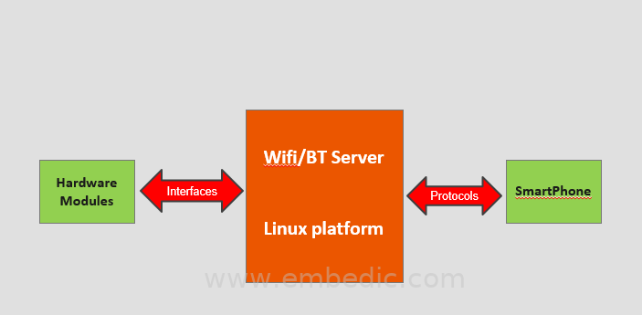
It can be seen that the modules developed by different personnel can run together and gradually integrate to run the entire system. All software of the server is written in C and compiled by mips-linux cross. The interface is written as an application, which can be called a new process. Here for this project, the server will use the infrared interface from the smartphone when it receives certain commands. This protocol is implemented inside the Wi-Fi/BT server and will be moved to a single file in the future to ensure flexibility. The smartphone will run the same protocol for communicating with the server. In order to ensure the stability of the connection, the server can connect to any Wi-Fi to activate the hotspot under the command of the smartphone, and try to reconnect when the connection is lost. Since the R Kai 266 system provides basic Wi-Fi services, the server will periodically check the connection status. All network tools used here are Linux cores. In some cases, the server will call the interface to complete different tasks.
2.4.2 Mobile software design
Currently, Android is the most popular mobile operating system. Flexible multi-platform support. In addition, our project relies on TCP communication, and Java is the ideal platform for TCP, so we choose Android as our client platform. The Android developer tools we use include Eclipse platform, JDT, CDT, EMF, GEF and WTP to develop our Android applications. Our Android application has four modes corresponding to the server program: Wi-Fi mode, connection mode, learning mode and control mode. Each of them is in an implementation thread. There is also a thread of a daemon that runs regularly to detect other services from the server. We parse the content in the UDP data packet and obtain the IP address of the server. In addition, our application needs to have a database that helps to store and maintain the learned materials. The communication between the smart phone and the hardware board has four modes: Wi-Fi, Connect, control and learning. They all have similar protocols, but implement different functions. Each mode has a corresponding button. The connection mode is the simplest communication between the client and the server. To check whether the connection between the smartphone and the server motherboard is good. It sends a TCP/IP message "hello:iniConnect". If it gets a valid result ("rdy:iniConnect"), the application will generate a message on the screen to tell if the connection is good. Otherwise, the app will tell the user that the connection failed. The Wi-Fi button contains information about the user's home or local wireless router, such as SSID and password, to connect the server motherboard to the local router. The figure below is the basic user interface of the smartphone application:
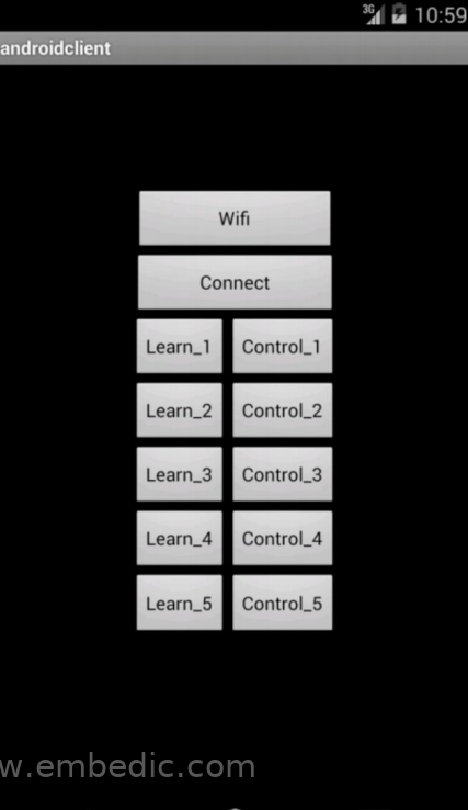
It shows a screenshot of the Android emulator. The Wi-Fi button executes the Wi-Fi mode. The connection button realizes the connection mode and checks the connection status. Learn_ * button action learning mode, and store the learned information in the database through the Control_ * button ID. Control the _* button to query the data in the database and send it to the circuit board. Each learning button has a corresponding control button. Once the learning protocol is completed, it will store the information obtained from the server in the local Android database: SQLite.
2.4.3 Linux Driver
One of the goals of this project is to realize Linux infrared transceiver. We also implement the I2C interface driver so that we can collect temperature, light and other sensor data. You can remotely control the TV, air conditioner, and speakers through your mobile phone. You can also make calls via the Internet and get feedback through the sensors to see if they are working properly. To understand how this system works, we should first understand some basic concepts of the Linux system.
*User space and kernel space
The most important concept of Linux programming is user and kernel space. The kernel space is the core of the operating system. It is used to execute processes and provide its services, especially its device drivers, which constitute the bridge or interface and hardware between end users/programmers. Since we are trying to manipulate the infrared transmitter and receiver, we must write a program that runs in the kernel. In Linux, a process is a running example program. We need to implement an application that indirectly controls the hardware in the user space.
*Linux driver
Linux operates the device as a file. On Linux, each piece of hardware is represented by a file that is located in /dev. Therefore, we can use fopen to open the device, use read and write functions to set and get data, and use ioctl functions for input and output control. There are two main types of equipment under all Linuix systems, character equipment and block equipment. A character device is a character device that does not perform buffering, and a block device is a device that does not perform buffering that is accessed through the cache. Since the character device is easier to implement and the infrared sensor does not require a lot of data, I decided to implement the infrared driver as a character device. Each character device driver has a file operation structure that declares the supported functions.
struct file_operations {
loff_t (* llseek) (structure file *, loff_t, int);
ssize_t (* read) (structure file *, char *, size_t, loff_t *);
ssize_t (* write) (structure file *, const char *, size_t, loff_t *);
int (* ioctl) (structure index node*, structure file*, integer without sign, unsigned long integer);
int (* open) (structure index node*, structure file*);
int (* release) (structure index node*, structure file*);
};
Description of each function:
llseek: Relocate the offset of the read and write files.
read: Read from file descriptor. We use this function to copy user space data from a buffer in kernel space.
write: write file descriptor. We use this function to write the kernel space buffer, so it can be sent by the infrared transmitter.
ioctl: Basic equipment parameters for processing special files. We use it to inform the transceiver when it should collect data and which transmission mode it uses.
open: When we use fopen to get the file descriptor, this function will be called. Some initialization is done here.
release: This function is called when we use fclose. The dynamically allocated buffer needs to be implemented here.
2.5 Embedded Server
The embedded server is the central control logic module on the hardware system. It has two main functions-providing network services and controlling the hardware interface. Network services are designed to communicate with smartphones and exchange commands and other information. The server can call the interface of other modules and send or collect information. This information can then be sent to the smartphone.
2.5.1 TCP/IP protocol
In our project, the communication between the smartphone and the hardware is mainly through TCP/IP (Transmission Control Protocol/Internet Protocol). This is the most basic agreement on the Internet, and defines how electronic devices access the Internet and how data can be disseminated. It has a four-level hierarchy, where each level calls a sub-level network to complete its task. In short, TCP's responsibility is to find problems in the transmission process and request retransmission until all data reaches the destination safely, and IP provides an address for each computer. TCP/IP has four levels of models, including: network interface layer, network layer, transport layer and application layer. There is another TCP/IP model that can divide the network interface layer into two layers: the data link layer and the physical layer.
*Network interface layer
The physical layer of the network interface layer defines the characteristics of the physical medium, such as mechanical properties, electronic properties, functional properties and program characteristics. This data link layer is responsible for receiving IP data packets and sending them through the network. Common interface protocols are: Ethernet 802.3, token ring 802.5, X.25, frame forwarding, HDLC, etc.
*Network layer
It is related to the communication between computers and has three functions.
(A) Process the RTS (request to send) from the transport layer and load it into the IP data packet, fill in the header, select the path to the target destination and send it to the appropriate interface.
(B) Arrange the input data packet and check its validity, and then route the data packet.
(C) Deal with routing, fluid control and jam issues.
*Transport layer
It provides communication between applications and their functions, including formatting information streams and providing reliable transmission. The main protocols of this layer are TCP and UDP (User Data Packet Communication Protocol).
*Application layer
It provides users with common applications such as email, file transfer, file access and Telnet. The main protocols of this layer are: FTP, TELNET, DNS, SMTP, NFS, HTTP.
Three, test
3.1 Hardware circuit test
For this project, our testing strategy is to first ensure that each individual module can work properly. Then we put them together to design a complete circuit diagram and PCB, and then test the final hardware system.
3.1.1 Single module test
First, we must ensure that the Wi-Fi module can operate normally. Since the Wi-Fi module is an existing board, it works very well and does not require much testing. Then we test the timer module to see if its output frequency is correct. We tested the circuit by connecting it with an oscilloscope and observed the output waveform. The result is that the frequency remains stable at 38 kHz with an error of approximately ±0.5 kHz. So the accuracy is about 98.6%. After adjusting the frequency and duty cycle to better values, we try to connect the timer input to the signal generator to see if the output follows. Then, we focused on testing infrared transmitting and receiving modules. To test the maximum infrared transmission range and coverage, we gradually move the transmission module and separate the receiver module until the signal on the receiver side disappears. The ADC and the sensor are tested together to see if the sensor is working and the conversion is correct. The picture below shows how we use a single IR test timer and infrared transmission module LED and a BJT. In addition, we tried to connect to the server and control the speaker phone of the remote control via Android. It can work normally within a distance of 5 meters. The infrared driver realizes two modes, namely the detection mode and the recording mode. The detection mode will detect whether the infrared signal is NEC and decode it. If the signal is not NEC, the driver records the waveform and sends the original data back to the server. Both modes are verified by an oscilloscope and integrated into the system. It has successfully controlled the TV and Speaker.
4.2 Embedded server test
Server testing is divided into two levels. The first level is a self-test using Fedora Linux over an Ethernet cable. All four basic functions have their own test cases, and we can see the correct response on the terminal. The control of the device is done through telnet on Windows. We can monitor and send some necessary commands to explain it. In theory, we can use any router as a hotspot. And the device has been successfully tested to connect TP-LINK router (TL-WR841N) and computer hotspot (via WiFi settings) Share Spirit) and smart phone hotspot (HTC ONE). In order to simplify the test, we use HTC ONE as a hotspot.
3.2.1 Self-check
The following is a self-check for each request:
IniWi-Fi:
iniConnection:
iniLearn: Since the self-check does not include IR hardware, the device returns the first response
rdy: ini study, and then wait for IR signal.
iniControl:
3.2.2 UDP broadcast test
We use the ARP application protocol to find hosts in the same network. After finding the host, it will send the data.
3.3 Smart phone software test
In order to ensure that the Android application can work as expected, we created some Linux server test cases corresponding to four modes. All test cases work in the same way. We run the server on the local computer and visit the IP address of the computer, and then change the SERVERIP using the Android code. Taking the WIFI mode as an example, first we let the smartphone connect to the same wireless network as the server, and then run our application. During the test, we output every I/O operation. We pressed the WIFI button, the server received "hello: iniWIFI" and responded with "rdy: iniWIFI". After Android receives the "rdy" message, it sends the pre-entered message SSID and password. The server outputs the obtained SSID and password, and then we check the result. We test four modes, all of which will produce correct results immediately, which means that the Android application can communicate with the server immediately. To test the learning mode, we created a server test case, once it receives "hello:iniLearn", it will send the content repository to the local "learn.ir" file. Then the smart phone stores the data in the database, and then outputs the content stored in the database to check whether the content in "lean.ir" is the same. The test control mode is the same as the learning mode, we click the control button to see if the server is in Get the same content in "learn.ir"
3.4 System test
For a complete system test, we only need to connect everything together and test other functions of the project through cooperation with team members, such as mobile application and hardware firmware development. They may just treat the hardware system as a lower-level platform that runs its functions.
4.5 Hardware driver test
We use learning commands and write the original code into a binary file. Then we read the file and resend the signal.

IC MCU 8BIT 80KB FLASH 52LQFP

IC MCU 16BIT 32KB FLASH 28SSOP
IC MCU 8BIT 32KB FLASH 64QFN

IC MCU 32BIT 256KB FLASH 44VTLA
1
2
3
4
5
6


Product updates, events, and resources in your inbox


Smart System

Traffic Management

Security

Consumer Electronics

Wireless Technology

Robot

Internet of Things

Industrial Control