Hello! Welcome to Embedic!
[Guide] introduction to the STM32F103C8T6 chip core board schematics, building a water lamp circuit, modification of the project template, code implementation, results display, a friend suggested to make a water lamp, and found that I had the STM32F103C8T6 development board I bought before, and build a water lamp today , Just to learn how to realize STM32 GPIO output.
·The use of STM32F103C8T6 smallest system board
·Breadboard method to build a water lamp circuit
· Modify the STM32F103RCT6 project template to the STM32F103C8T6 project template
·Familiar with the use of STM32 MCU GPIO as output
According to the STM32&STM8 product model naming rules (reference: STM32 microcontroller minimum system details), we can know:
In the naming of STM32F103C8T6:
STM32 stands for STM32 family, 32-bit MCU;
·F stands for the basic product type;
·103 represents that the specific function is STM32 basic;
·C represents the number of pins is 48&49 pins;
·8 means the memory capacity is 64KB;
·T stands for QFP package;
·6 represents the temperature range of -40 to +85°C.
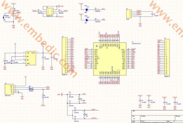
Through the schematic diagram we can know:
·There are two ways of board power supply:
· Provide 5V power supply through the U3 USB-micro interface, and then convert it to VCC3V3 through the onboard LDO chip;
·Power supply to the core board through the P2 interface, that is, VCC3V3 in the SWD download interface.
There are two LEDs on the core board, one of which is the power indicator PWR, and the other is connected to the PC13 pin. When PC13 is set high, the LED is off; when PC13 is set low, the LED is on;
·The jumper on the core board is used to select the startup mode. In order for the program to use the main flash memory as the boot area, we need to set BOOT0 low and BOOT1 at will. This boot mode is the most commonly used user FLASH boot, which is the default boot mode;
·The button on the core board is the RESET button;
·P2 interface is the pin interface corresponding to SWD download mode;
·Prepare components
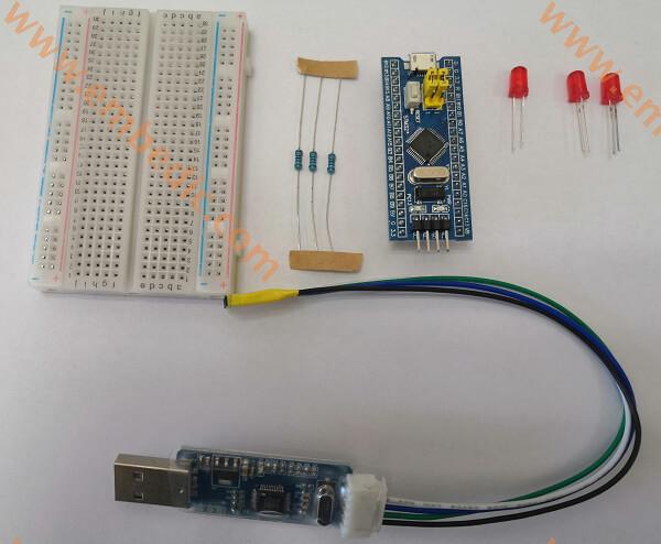
note:
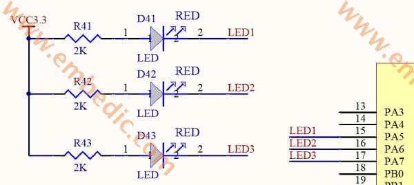
The resistance used is 2K, which is used as a current limiter;
Pay attention to the positive and negative poles of the LED. Insert the LED directly. The long pin is the positive pole and the short one is the negative pole; if the pins are cut, they are the same length. Check the size of the metal pole inside the LED tube. The metal pole is smaller. It is the positive electrode, and the large sheet is the negative electrode.
·Build the circuit
Build the circuit according to the following schematic
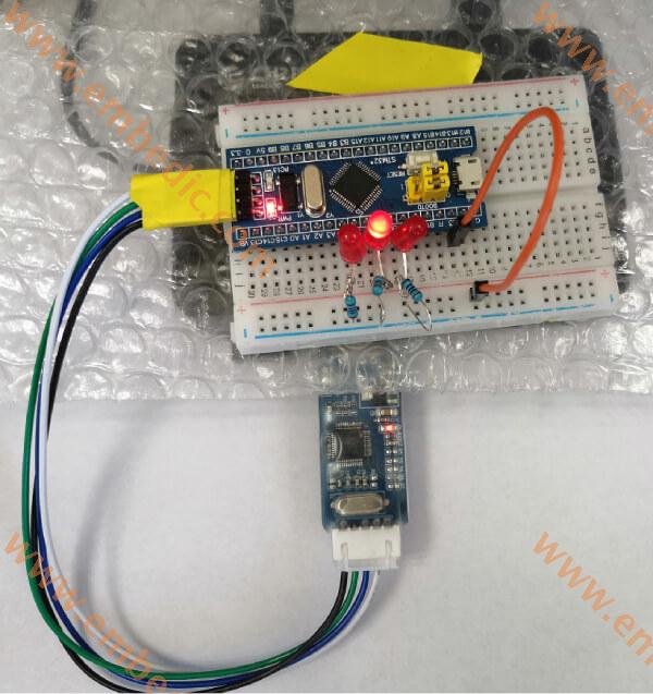
·STM32F103C8T6 mini development board completed renderings

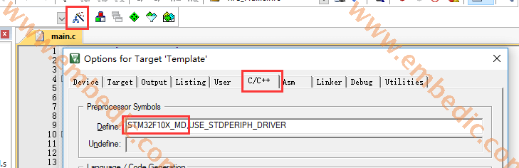
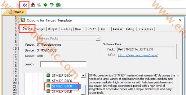
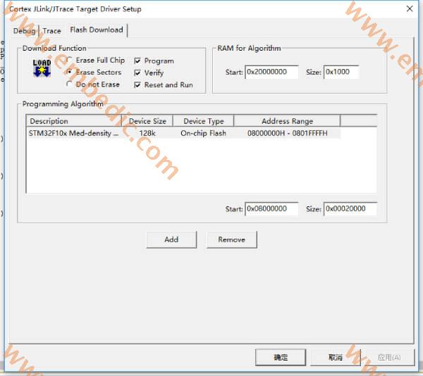
Based on the establishment of the MDK5 project based on the STM32 firmware library, the STM32F103RCT6 project template was modified to the STM32F103C8T6 project template. Modification points:
·Replace the startup file, replace startup_stm32f10x_hd.s with startup_stm32f10x_md.s, startup_stm32f10x_md.s is the startup file for medium capacity products, the corresponding FLASH size range is: 64K≤FLASH≤128K.
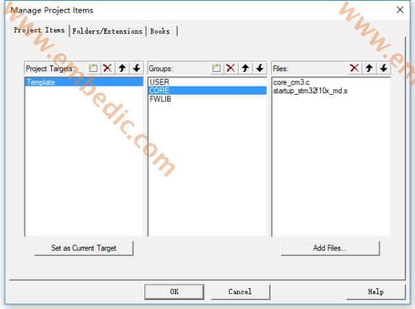
·Modify the global macro definition, change STM32F10X_HD to STM32F10X_MD.
·Change the chip model used
·Set the download Flash capacity
Note: STM32F103C8T6 and STM32F103CBT6 are manufactured on the same wafer, but when testing, only the content contained in the parameter range provided in the manual is tested, which means that STM32F103C8T6 is also 128k Flash, but only the previous 64k is tested, and then STM32F103C8T6 Mark (Of course, the ID of C8T6 is written inside); so when we add Flash, we can only find 128K STM32F103, but can not find 64K Flash.
·Set PA5, PA6, PA7 as output
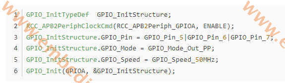
·Initialize GPIO to high level, when high level, LED is off
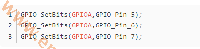
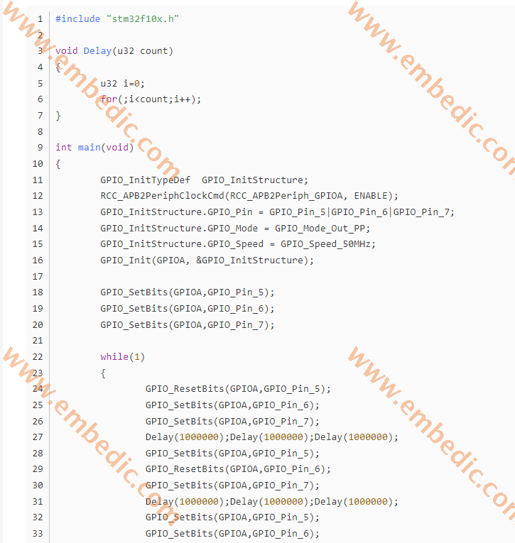
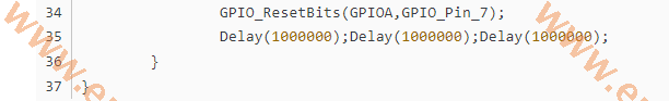
·The specific realization of the code of the water lamp
Manufacturer: Texas Instruments
IC DSP FIXED-POINT 688FCBGA
Product Categories: DSP
Lifecycle:
RoHS:
Manufacturer: Texas Instruments
IC DSP FIXED-POINT 688FCBGA
Product Categories: DSP
Lifecycle:
RoHS:
Manufacturer: Texas Instruments
IC MCU 16BIT 2KB FLASH 14TSSOP
Product Categories: 16bit MCU
Lifecycle:
RoHS:
Manufacturer: Microchip
IC MCU 8BIT 7KB FLASH 28SSOP
Product Categories: 8bit MCU
Lifecycle:
RoHS:
Looking forward to your comment
Comment
1
2
3
4
5
6
 Popular Searches
8 Bit MCU, Flash, PIC16 Family PIC16F7XX Series Microcontrollers, 20 MHz, 7 KB, 192 Byte, 44 Pi...
EEPROM 2K 256 X 8 2.5V SERIAL EE IND
System-On-Modules - SOM RCM2200
32-bit Arm Cortex-A53 vision processor with ISP, powerful 3D GPU, dual APEX-2 vision accelerat...
IC MCU 8BIT 60KB FLASH 44QFP
DSP 20MHZ 44QFP
Product updates, events, and resources in your inbox


Smart System

Traffic Management

Security

Consumer Electronics

Wireless Technology

Robot

Internet of Things

Industrial Control


