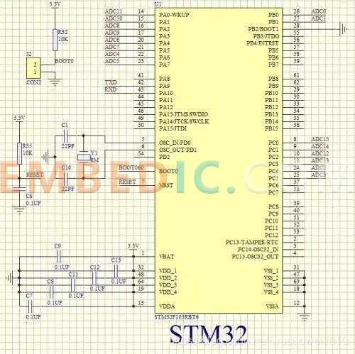
The STM32 microcontroller has 8 IO port modes: analog input, floating input, pull-up input, pull-down input, open-drain output, push-pull output, multiplexed open-drain output and multiplexed push-pull output.

1、Analog Input
GPIO_Mode_AIN analog input, i.e., close the Schmitt trigger and pass the voltage signal to the on-chip peripheral module (without connecting pull-up and pull-down resistors).
2、Float input
GPIO_Mode_IN_FLOATING floating input. Floating input state, the level state of IO is indeterminate, completely determined by the external input, if in the case of the pin is suspended, reading the level of the port is indeterminate.
3&4, pull-up and pull-down input
GPIO_Mode_IPD pull-down input, GPIO_Mode_IPU pull-up input. Generally speaking, the pull-up resistor is 1K-10K, the smaller the resistance, the stronger the driving capability.
The role of the resistor: to prevent the input from overhanging, to reduce the interference of external current to the chip, to limit the current, and to increase the driving ability when the high level output.
When there is no input on the GPIO pin, the pull-up input is high in the default state and the pull-down input is low in the default state.
5、Open-drain output
GPIO_Mode_Out_OD open-drain output, the output terminal is equivalent to the collector of the triode. To get a high state requires a pull-up resistor to work. Suitable for doing current type drive, its ability to absorb current is relatively strong, generally within 20mA.
6、Push-pull output
GPIO_Mode_Out_PP push-pull output, can output high and low level, connected to digital devices.
7&8、Multiplexed open-drain push-pull output
GPIO_Mode_AF_OD multiplexed open-drain output, GPIO_Mode_AF_PP multiplexed push-pull output. It can be understood as the configuration case when the GPIO port is used as a second function, i.e. not as a general-purpose IO port.
IO mode selection
Floating input: can do KEY identification, RX1.
Pull-up input: IO internal pull-up resistor input.
Pull-down input: IO internal pull-down resistor input.
Analog input: Application ADC analog input, or power saving under low power consumption.
Open-drain output: IO output 0 is connected to GND, IO output 1, dangling, requires external pull-up resistor to achieve high output level. When the output is 1, the state of IO port is pulled high by the pull-up resistor, but because it is open-drain output mode, so that the IO port can also be changed to low or unchanged by the external circuit. It is possible to read IO input level change and realize the IO bidirectional function of C51.
.jpg)
Push-pull output: IO output 0 - connected to GND, IO output 1 - connected to VCC, read input value is unknown.
Multiplexed push-pull output: on-chip and off-chip functions, SCL and SDA of I2C.
Multiplexed open-drain output: on-chip and off-chip functions, TX1, MOSI, MISO.SCK.SS.
There are usually five ways to use a pin function, and they are configured as follows.
1.As normal GPIO input: Configure the pin as floating input, with weak pull-up input or with weak pull-down input as needed, and do not enable all the multiplexed function modules corresponding to the pin.
2.As ordinary GPIO output: configure the pin as push-pull output or open-drain output as needed, and do not enable all the multiplexed function modules corresponding to the pin.
3.As a normal analog input: configure the pin as analog input mode, and do not enable all the multiplexed function modules corresponding to the pin.
4.As input of built-in peripheral: configure this pin as floating input, with weak pull-up input or with weak pull-down input as needed, and enable one of the multiplexer modules corresponding to this pin.
5.As the output of built-in peripheral: configure the pin as multiplexed push-pull output or multiplexed open-drain output as required, and enable all the multiplexed function modules corresponding to the pin.
Manufacturer: Texas Instruments
IC DIGITAL MEDIA SOC 529FCBGA
Product Categories: SOC
Lifecycle:
RoHS:
Manufacturer: Analog Devices
IC DSP 16/32B 400MHZ 168CSBGA
Product Categories: DSP
Lifecycle:
RoHS:
Manufacturer: Analog Devices
IC DSP 16/32B 400MHZ 168CSBGA
Product Categories: DSP
Lifecycle:
RoHS:
Manufacturer: Microchip
IC MCU 8BIT 8KB FLASH 20SOIC
Product Categories: 8bit MCU
Lifecycle:
RoHS:
Looking forward to your comment
Comment