Hello! Welcome to Embedic!
Today we teach you to make a magnetic levitation toy.
There are two basic forms of magnetic levitation: push-down and pull-up.
The so-called down-push type, that is, the control part in the base, levitation of the magnet in the above, relying on the base from the bottom to the top of the repulsive magnetic force to push the magnet levitation; and pull-up type, is the control part in the top, levitation of the magnet in the bottom, relying on the control part from above the attraction of the magnet will not fall down.
In this paper, we realize the down-push type, and only explain the principle and implementation method of down-push magnetic levitation.
The following figure shows the magnetic line of a ring magnet.
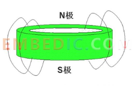
If another small magnet is placed above it, with the N pole down and the S pole up, then it will be repelled by the ring magnet below. The closer to the ring magnet below, the greater the repulsive force. When the distance is right, the repulsive force is equal to the gravity of the magnet above, then levitation can be achieved:
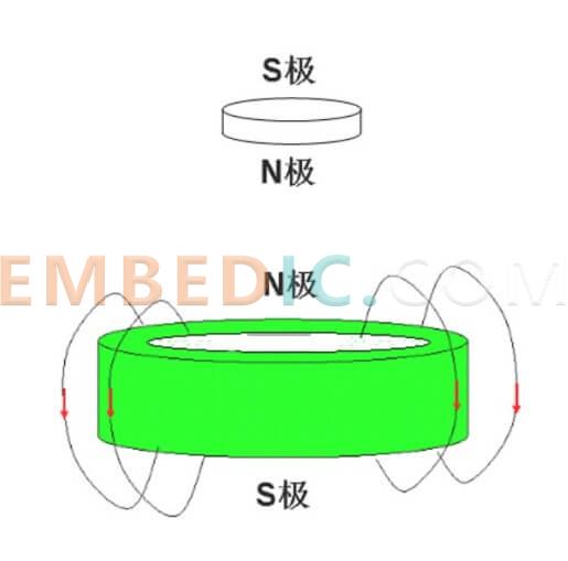
However, the interaction of the two magnets alone cannot maintain stability, because the repulsive force of the two magnets cannot be balanced as long as the direction of gravity is not in the same line, and the small magnet above will fly out to the side.
The downward pushing magnetic levitation method is to add a device to control the upper small magnet to keep in the central axis position in the above system. In this way, the small magnet cannot move to the side, and the gravity in the vertical direction and the magnet repulsion cancel, so that a stable levitation can be achieved.
If there is no large ring magnet, you can use a circle of small magnets instead, the effect is the same, such as the effect of this article in the picture with 4, 8 can, but must be arranged in a symmetrical position.
The device to control the position of small magnets, generally composed of Hall elements and electromagnets. Two Hall components are used to detect the magnetic field, and the two Hall elements are mounted at the center of the ring magnet and are perpendicular to each other, with the detection surface parallel to the plumb line.
If the small magnet above is on the central axis, then the magnetic lines of force of the system are also in the plumb line direction, and both Hall components have no output; if the small magnet deviates from the central axis, then the magnetic lines of force direction of the system will deviate from the plumb line direction, and the Hall components will be able to detect the deviation in a certain direction. At this point, the MCU collects the output of the Hall element, controls the electromagnet, generates a magnetic force in the opposite horizontal direction, and just pulls the small magnet back to the central axis.
Since the system is a dynamic balance system, it needs to be constantly collected, judged and adjusted, and it is best to use PID control.
Understand the principle, the following together to achieve it.
By the principle explained above, our hardware only needs to deal with two things on the line: one is to collect the output of two mutually perpendicularly mounted Hall elements to obtain the offset position of the small magnet; the second is to control two sets of mutually perpendicular electromagnets to generate horizontal magnetic force.
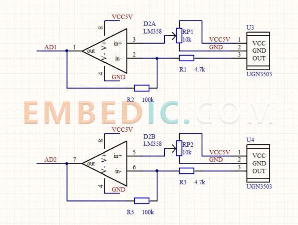
Hall element and its signal amplification part, UGN3503 is the Hall component, potentiometer to provide an initial zero voltage, Hall's output signal through the reverse amplification, output to the STM32's AD port to collect.
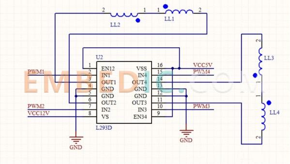
Solenoid drive part, using L293D motor driver chip to drive the solenoid, L293D by the STM32 output PWM wave to drive.
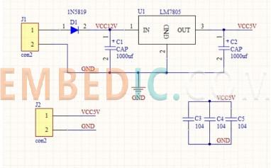
Power supply part, drive the solenoid with a voltage of 9 ~ 12V is more appropriate, Hall power supply with 5V:.
Because the small white white in DIY when the STM32 is an external minimum system, so the schematic diagram did not draw the STM32, leaving only a few contacts.
Note the layout, the placement of Hall components and solenoids, there are special requirements. The final PCB diagram is as follows.
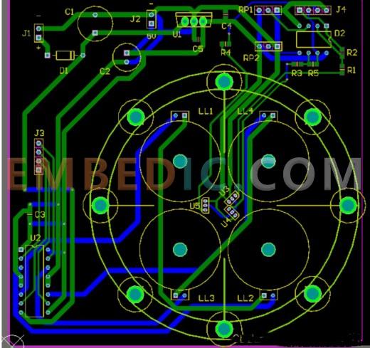
U3 and U4 are two Hall elements to detect the position of the magnet, need to be installed near the center of the ring magnet, and perpendicular to each other; and the plane of the Hall to be on the line of the opposite corner solenoid.
Note the location of the two Hall U3 and U4: (U5 is also a Hall, originally reserved to detect whether there is a magnet placed on it, not used for the time being)
LL1 ~ LL4 are four electromagnets, LL1 and LL2 group, LL3 and LL4 group, the installation, the same group needs to be placed diagonally; and to pay attention to the installation of the same name end connected, after power, the same group of two electromagnets magnetic lines can be connected to each other to produce closed magnetic lines (that is, one above the N pole when the other above the same group for the S pole). This will ensure that the magnetic force generated by the same group of electromagnets is the same in the horizontal direction.
After the circuit diagram is soldered, connected to the STM32F103C8T6 minimum system, Hall's output AD1, AD2 connected to the STM32's PA0 and PA1; PWM1~4 connected to the STM32's PA15, PB4, PB3, PB5 in turn. other power supply parts of the connection will not be mentioned.
After installing the ring magnet and powering up, adjust the potentiometers connected to U3 and U4 under no-load condition so that both AD1 and AD2 are around 1.65V (i.e. the middle of 3.3V for AD acquisition).
Here, the hardware design work is basically completed.
The software implementation is also roughly divided into two major functions: first, through the AD acquisition, to obtain the position of the magnet and then the horizontal direction of the X and Y axis; second, through the size of the two directional position offset to calculate the value of the PWM output to drive the two directions of the electromagnet, this calculation process uses the PID algorithm.
The program architecture is: in the main loop to continuously collect the voltage of the Hall element, that is, the value of AD1, AD2; in the interrupt to calculate the PID control algorithm, set the PWM output.
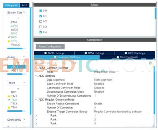
First, configure the ADC in cubemx, turn on AD0, AD1 and AD4 (actually only AD0 and AD1 are used, AD4 is reserved, acquired but not used for calculation), configure to rank1, rank2 and rank3 in the figure respectively.
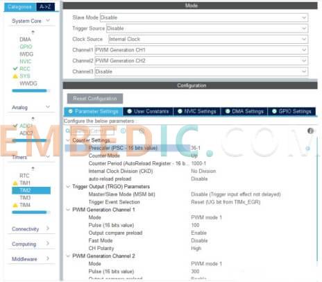
Enable timer TIM2 interrupt.
Here, the main configuration of the hardware in cubemx is completed. Next, you can generate the keil project and write the software code.
In the keil project, the adc part, the following function is used for AD acquisition, three channels are acquired, namely AD0, AD1, AD4.
Then sliding average filtering is performed, and here only two channels, AD0 and AD1, with 10bit precision, are finally retained and stored in xPos and yPos as position values in both directions.
The filter_adc() function needs to be called in a loop in the main loop to continuously update the position values.
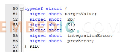
The main implementation code for the PID part is as follows.
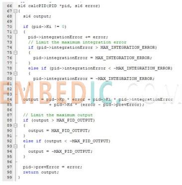
Note here the treatment of the integral term in the PID implementation, when the cumulative value of the error is very large (i.e., when the integral term is large) will not be added to the error term, but limited to a maximum MAX_INTEGRATION_ERROR, which is a way to avoid integral saturation. (For the integral saturation of PID, please refer to the previous article "In-depth Discussion of PID Control (Position PID, Incremental PID, and Integral Saturation of PID)")
Next, talk about how to set the PWM output value, and how to control the positive and negative direction of the magnetic field of the solenoid.
As we use the L293D chip to drive the solenoid, LL1 and LL2 this way for example, when PWM2 is set to low, then PWM1 output is high when it can drive the solenoid; when PWM2 is set to high, then PWM1 output is low, the current is opposite to the aforementioned state, it can drive the solenoid in reverse. As shown in the figure below.
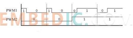
Meanwhile, we only need to change the pulse width of PWM1 to realize the magnetic field strength control of the electromagnet.
The other way LL3 and LL4 solenoids are also the same principle, you can control the magnetic field strength by PWM3 and the magnetic field direction by PWM4.
The implementation code of this part is as follows, where the output values of PWM1 and PWM3 (that is, the xPWM and yPWM in the code) are derived by calling the PID calculation function, and then set to the PWM output of the timer according to the positive and negative direction, and the whole function is placed in the timer interrupt call.
Finally, remind, the PID parameter values, which need to be adjusted, these values are related to the magnet size and the control cycle length of the timer, the values in this paper are taken as follows.
#define P_value 4
#define I_value 1
#define D_value 30
In debugging, you can first hold the small magnet from the top to move down, when the feeling of gravity is offset by the magnetic force, and then move to the horizontal X, Y direction, if the feeling of horizontal resistance, then a large part of the success, the later only need to fine-tune the parameters. Be careful to protect the strong magnet, if the two magnets are not protected directly sucked together is likely to be smashed.
Here, the most basic function of magnetic levitation is done, but there are still many places that can be optimized.
For example, now the calculation period used is 2KHz, just within the range of human hearing, which in use, the solenoid may produce some noise, you can consider changing the control period to more than 20KHz, but pay attention to the PID parameters need to be adjusted.

Manufacturer: Texas Instruments
IC DSP FIX/FLOAT POINT 176HLQFP
Product Categories: DSP
Lifecycle:
RoHS:
Manufacturer: Texas Instruments
IC DSP FIXED/FLOAT POINT 256BGA
Product Categories: DSP
Lifecycle:
RoHS:
Manufacturer: Texas Instruments
IC DSP FIXED/FLOAT POINT 256BGA
Product Categories: DSP
Lifecycle:
RoHS:
Manufacturer: Texas Instruments
IC DSP FIX/FLOAT POINT 176HLQFP
Product Categories: DSP
Lifecycle:
RoHS:
Looking forward to your comment
Comment
1
2
3
4
5
6
 Popular Searches
8 Bit MCU, Flash, PIC16 Family PIC16F7XX Series Microcontrollers, 20 MHz, 7 KB, 192 Byte, 44 Pi...
EEPROM 2K 256 X 8 2.5V SERIAL EE IND
System-On-Modules - SOM RCM2200
32-bit Arm Cortex-A53 vision processor with ISP, powerful 3D GPU, dual APEX-2 vision accelerat...
IC MCU 8BIT 60KB FLASH 44QFP
DSP 20MHZ 44QFP
Product updates, events, and resources in your inbox


Smart System

Traffic Management

Security

Consumer Electronics

Wireless Technology

Robot

Internet of Things

Industrial Control


