Hello! Welcome to Embedic!
Nowadays, we can find IIC (Inter-Integrated Circuit) and SPI (Serial Peripheral Interface) everywhere in low-end digital communication applications. Philips (for IIC) and Motorola (for SPI) have developed these two standard communication protocols for different backgrounds and market needs.
IIC was developed in 1982 to provide a simpler way to interconnect the CPU and peripheral chips inside a TV. TVs were among the first embedded systems, and the original embedded systems used memory-mapped I/O to interconnect microcontrollers and peripherals. To achieve memory-mapped, devices must be connected in parallel to the data and address lines of the microcontroller, which is inconvenient and costly because of the large number of lines and additional address decoder chips required to connect multiple peripherals.
In order to save microcontroller pins and additional logic chips and to make the printed circuit board simpler and less expensive, Philips Laboratories in the Netherlands developed the "Inter-Integrated Circuit", IIC or I2C, a protocol that uses only two wires to connect all peripheral chips. bus protocol using only two wires to connect all peripheral chips. The original standard defined a bus speed of 100 kbps, which was revised several times, mainly to 400 kbps in 1995 and 3.4 Mbps in 1998.
There are indications that the SPI bus was first introduced in 1979 when Motorola integrated the SPI bus into their first microcontroller chip adapted from the 68000 microprocessor, which is a four-wire external bus (as opposed to an internal bus) for microcontrollers. Unlike the IIC, the SPI has no explicit standard, only a de facto standard, and the implementation of communication operations is described in general abstraction, with chip manufacturers and driver developers communicating implementation details through data sheets and application notes.
Interconnecting two digital devices with SPI is fairly intuitive for experienced digital electronics engineers. SPI is a four-signal line protocol (as shown in Figure 1).
SCLK: Serial Clock (output from master);
MOSI; SIMO: Master Output, Slave Input;
MISO; SOMI: Master Input, Slave Output;
SS: Slave Select (active low).
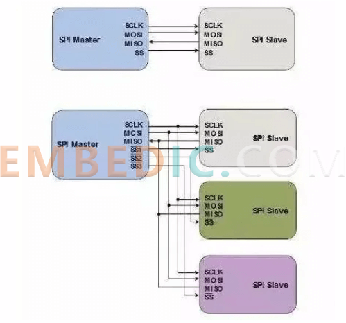
SPI is a single-master communication protocol, which means that only one central device in the bus can initiate communication. When the SPI master device wants to read/write the slave device, it first pulls down the SS line corresponding to the slave device (SS is active low), then starts sending working pulses to the clock line, and at the corresponding pulse time, the master device sends the signal to MOSI to achieve "write", and at the same time, it can sample MISO to achieve "read".
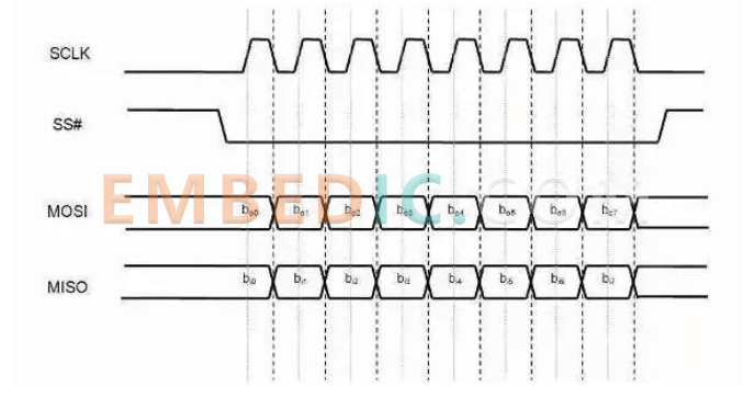
SPI has four modes of operation: mode 0, mode 1, mode 2 and mode 3. The difference between them is that they define which edge of the clock pulse converts (toggles) the output signal, which edge samples the input signal, and the stable level value of the clock pulse (i.e., whether it is high or low when the clock signal is invalid). Each mode is portrayed by a pair of parameters called clock polarity (clock polarity) CPOL and clock phase (clock phase) CPHA.
Master and slave devices must use the same operating parameters - SCLK\CPOL and CPHA - in order to work properly. If there are multiple slave devices and they use different operating parameters, then the master device must reconfigure these parameters between reading and writing different slave devices.
SPI does not specify a maximum transfer rate and has no address scheme; nor does SPI specify a communication answer mechanism or flow control rules. In fact, the SPI master device does not even know if the specified slave device exists. These communication controls have to be implemented outside the SPI protocol itself. For example, to connect a "command-response-controlled" decoder chip using SPI, a higher-level communication protocol must be implemented on top of SPI.
SPI does not care about the electrical characteristics of the physical interface, such as the standard voltage of the signal. Initially, most SPI applications used intermittent clock pulses and transferred data in byte units, but now there are many variants that implement continuous time pulses and data frames of arbitrary length.
Unlike SPI's single master device, IIC is a multi-master device bus. IIC has no physical chip select signal lines, no arbitration logic circuitry, and uses only two signal lines - serial data (SDA) and serial clock (SCL).
IIC data transfer rates are standard mode (100kbps), fast mode (400kbps) and high speed mode (3.4Mbps), and some other variants implement low speed mode (10kbps) and fast+ mode (1Mbps).
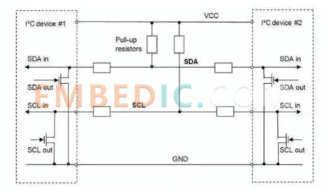
Physically implemented, the IIC bus consists of two signal lines and one ground line. Both signal lines are bi-directional, refer to Figure 3. The IIC protocol standard specifies that the device initiating communication is called the master device, and after the master device initiates communication once, all other devices are slaves.
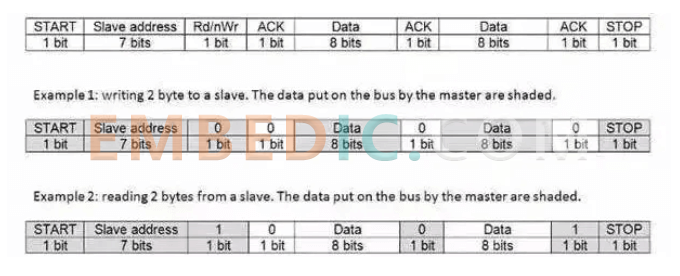
The IIC communication process is approximately as follows. First, the master device sends a START signal, which is like shouting to all other devices: Please pay attention! Then the other devices start listening to the bus to prepare for receiving data. Then, the master device sends a data frame with 7-bit device address plus one bit for read/write operation. When the device receives the data, it compares the address with itself to see if it is the target device. If the comparison does not match, the device enters the wait state, waiting for the arrival of the STOP signal; if the comparison matches, the device will send an answer signal - ACKNOWLEDGE for response.
When the master device receives the answer, it starts to transmit or receive data. The data frame size is 8 bits, followed by a one-bit answer signal. The master device sends data and the slave device answers; on the contrary, the master device receives data and the master device answers. When the data transmission is finished, the master device sends a STOP signal to announce the release of the bus to the other devices, and the other devices return to the initial state.
Based on the physical structure of the IIC bus, the START and STOP signals on the bus must be unique. In addition, the IIC bus standard stipulates that the data transition of SDA line must be in the low level period of SCL line, and the upper data of SDA line is stable in the high level period of SCL line.
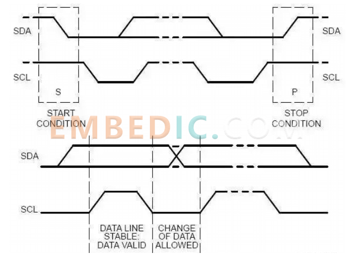
In the physical implementation, both SCL line and SDA line are open-drain (open-drain) with an additional voltage source through a pull-up resistor. Based on these characteristics, the IIC device operates on the bus only by "grounding the line" - outputting a logic 0.
The IIC bus design uses only two lines, but it is quite elegant and perfect for seamless communication between any number of devices. Imagine what would happen if two devices sent information to the SCL and SDA lines at the same time.
Based on the design of the IIC bus, there is no possibility of level conflict on the line. If one device sends a logic 0 and the other sends a logic 1, then the line sees only a logic 0. That is, if there is a level conflict, the one sending the logic 0 is always the "winner".
The physical structure of the bus also allows the master device to read data while writing to the bus. In this way, any device can detect the occurrence of a conflict. When two masters compete for the bus, the "winner" is not aware of the competition, and only the "loser" discovers the conflict - when it writes a logical 1 and reads a 0 - and quits the competition. --and withdraws from the competition.
Ten-bit device address
Any IIC device has a 7-bit address, and in theory, there can only be 127 different IIC devices in reality. In practice, there are far more types of IIC devices available than this limit, and the probability of having IIC devices with the same address on a bus is quite high. In order to break this limit, many devices use dual addresses - 7-bit addresses plus pin addresses (external configuration pins). the IIC standard also foresees this limitation and proposes a 10-bit address scheme.
The impact of the 10-bit address scheme on the IIC protocol is twofold.
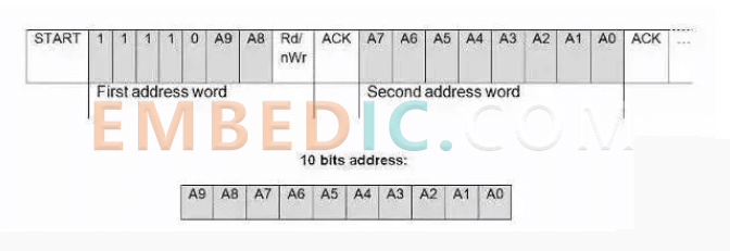
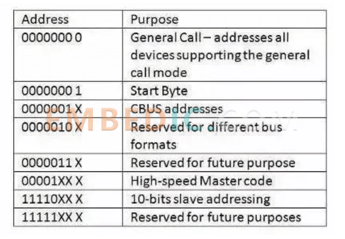
In addition to the 10-bit address identifier, the standard also sets aside some address codes for other purposes, as follows.
Clock Stretching
In IIC communication, the master device determines the clock speed. This is because the clock pulse signal is sent explicitly by the master device. However, when the slave device is not able to keep up with the speed of the master device, the slave device needs a mechanism to request the master device to slow down a bit, this mechanism is called clock stretching. This mechanism is implemented based on the specificity of the IIC architecture. When the slave device needs to slow down the speed of transmission, it can press the clock line, forcing the master device into a wait state until the slave device releases the clock line and communication continues.
High-speed mode
In principle, using pull-up resistors to set logic 1 will limit the maximum transmission speed of the bus. And speed is one of the factors limiting the application of the bus. This explains why high-speed mode (3.4Mbps) is introduced. Before initiating a high-speed mode transfer, the master device must first send a specific "High Speed Master" signal in a low-speed mode (e.g. fast mode). In order to shorten the signal period and increase the bus speed, the high-speed mode must use additional I/O buffers. In addition, bus arbitration can be masked out in High Speed mode. For more information, please refer to the bus standard documentation.
Let's compare some key points of IIC and SPI.
1 Bus topology \ signal routing \ hardware resource consumption
IIC requires only two signal lines, while standard SPI requires at least four signals, and more if there are multiple slave devices. Some SPI variants use only three lines-SCLK, SS, and bidirectional MISO/MOSI-but the SS line still has to be one pair with the slave device. In addition, if SPI is to implement a multi-master device architecture, the bus system requires additional logic and lines. The only problem with building a system bus with IIC is the limited 7-bit address space, but this problem has been solved by the new standard - using 10-bit addresses. From the first point of view, IIC is the obvious big winner.
2 Data Throughput \ Transfer Speed
If the application must use high-speed data transfer, then SPI is the obvious choice. Because SPI is full duplex, IIC's is not. SPI has no defined speed limit, and general implementations can usually reach or even exceed 10 Mbps. the highest IIC speeds are just Fast+ mode (1 Mbps) and High Speed mode (3.4 Mbps), and the latter modes require additional I/O buffers, which are not always easy to implement yet.
3 Elegance
IIC is often said to be more elegant than SPI, but to be fair, I prefer to think that both are equally elegant and robust, and IIC's elegance lies in its feature of implementing multi-master device arbitration and device routing in a very lightweight architecture. However, it is more difficult for the engineer using it to understand the bus structure, and the bus performance is not high.
The advantage of SPI is that its structure is fairly intuitive and simple, easy to implement, and very scalable. the simplicity of SPI is not enough to call it elegant, because to build a useful communication platform with SPI, you also need to build specific communication protocol software on top of SPI. This means that it takes more work for engineers to get the high-speed performance, a feature unique to SPI but not to IICs. Both IIC and SPI provide good support for low-speed device communication, but SPI is suitable for data stream applications, while IIC is more suitable for "byte device" multi-master applications.
In the digital communication protocol cluster, IIC and SPI are often referred to as "small" protocols, compared to Ethernet, USB, SATA, PCI-Express, and other buses with transmission speeds of hundreds of gigabytes per second. However, what we must not forget is what the various buses are used for. The "big" protocol is used for communication between the whole system outside the system, and the "small" protocol is used for communication between chips inside the system, and there is no indication that the "big" protocol is necessary to replace the "small" protocol. "The existence and popularity of IIC and SPI reflects the philosophy of "enough is enough". In response to the top of the article, IIC and SPI are so popular that it is a must-have tool for any embedded engineer.
Manufacturer: Texas Instruments
IC DSP FIXED-POINT 737FCBGA
Product Categories: DSP
Lifecycle:
RoHS:
Manufacturer: Texas Instruments
IC DSP FLOATING POINT 256BGA
Product Categories: DSP
Lifecycle:
RoHS:
Manufacturer: Microchip
IC MCU 8BIT 32KB FLASH 44QFN
Product Categories: 8bit MCU
Lifecycle:
RoHS:
Manufacturer: Microchip
IC MCU 8BIT 16KB FLASH 28UQFN
Product Categories: 8bit MCU
Lifecycle:
RoHS:
Looking forward to your comment
Comment
1
2
3
4
5
6
 Popular Searches
8 Bit MCU, Flash, PIC16 Family PIC16F7XX Series Microcontrollers, 20 MHz, 7 KB, 192 Byte, 44 Pi...
EEPROM 2K 256 X 8 2.5V SERIAL EE IND
System-On-Modules - SOM RCM2200
32-bit Arm Cortex-A53 vision processor with ISP, powerful 3D GPU, dual APEX-2 vision accelerat...
IC MCU 8BIT 60KB FLASH 44QFP
DSP 20MHZ 44QFP
Product updates, events, and resources in your inbox


Smart System

Traffic Management

Security

Consumer Electronics

Wireless Technology

Robot

Internet of Things

Industrial Control


