Hello! Welcome to Embedic!
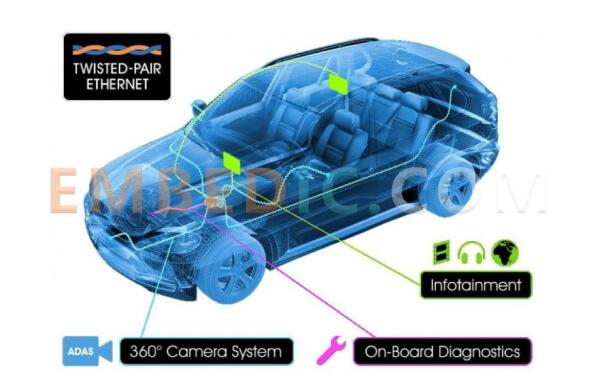
With the advent of smart Internet connectivity in cars, data transmission for entertainment systems and advanced driver assistance systems (ADAS) is becoming more and more important, and the emergence of automotive Ethernet carries a higher demand for future data transmission. In this issue, embedic will take you through a discussion on transmission channel hardware.
In addition to the commercial battles between vendors, the choice between unshielded and shielded hardware has always been a source of confusion and debate among users. The source of all the confusion and debate lies in the description of the transmission link in BroadR-Reach, "The one pair UTP cable" (single pair unshielded twisted pair), which can support each link to meet 100Mbps transmission at the same time.
I agree that in the "stable" transmission of 100Mbps "without electromagnetic interference environment", unshielded system can do such work. However, we also found some phenomena in the actual channel transmission study, which I hope to draw the reader's attention and consideration. First, in terms of SI (signal integrity), there are many forms of unshielded cable topologies. Two common types are unshielded twisted pair with bare uninsulated cover and unshielded twisted pair with integral fastened insulated cover.
Using these two forms to match the system, the transmission will produce different effects: 1. without a single insulated twisted pair in the vehicle assembly may occur due to worker error back twisted situation, once it happens, will seriously affect the overall characteristic impedance. 2. for the different use of the environment, we simulated two scenarios.
(1) First, we only put our hands on the cable (touch only), for the cable without a single insulation, due to the change in the dielectric constant between the two cables, after the touch, the characteristic impedance of the channel occurred significantly larger fluctuations, and even exceed the standard (TC2) requirements.
(2) We also tried more severe conditions, put the cable in water, simulating a highly humid environment, without a one-piece insulation outside the channel characteristic impedance exceeded the standard value is greater than before. In both experiments, the characteristic impedance of the cable with the one-piece outer cover was always more stable. The reason for discussing the above situation is that the standards, including BroadR-Reach, do not mention the specific state of the cable, and many manufacturers prefer to choose unshielded twisted-pair cable without one-piece outer cover due to cost considerations, then in the actual use of the process, due to changes in the environment, there is the possibility of greater reflection of the signal. In addition, for the channel EMC situation, that is, the standard mentioned in the WCC contains ES (Environmental System) test scenarios, there are also the following phenomena need to pay attention to. 1.
1. The phenomenon mentioned in TC9, in the test of unshielded cable crosstalk, if observed from the cable along the radial split interface, two pairs of stranded wires as (b) placed (stranded pairs are located in the plane perpendicular to each other), the resulting crosstalk value will be the minimum case under the arrangement; if placed (c) (stranded pairs are located in the plane parallel to each other), the resulting crosstalk value will be the maximum case under the arrangement. The crosstalk value will be the maximum case under the arrangement.
And please note that, for unshielded twisted pair, in practice, due to the aforementioned use of a one-piece insulated cover, and the inability to really cut open the cable to observe the situation of the arrangement bundle is random, there may be the same situation, due to changes in the relative position of the two wires twisted, resulting in the actual transmission effect of different situations.
2. The phenomenon is not mentioned in any standards. In automotive harness layouts, it is very common for multiple strands to be bundled together. When at least two strands of unshielded twisted pair cable are bundled together, we find that if the two strands of cable stranded exactly right, that is, the stranded wire similar to the "open eye" exactly right, as shown (b), (this figure to illustrate the situation is not drawn outside the insulation, the actual cable with a single insulation), the measured foreign distal crosstalk value will If the two strands are stranded at exactly the wrong place, i.e., as shown in (c) (this figure is not shown to illustrate the situation, the actual cable has a single insulated outer cover), the measured foreign remote crosstalk value is reduced to a minimum in the same situation.
However, due to the actual state, the use of unshielded cable with a one-piece insulating cover, it is impossible to determine the relative position of the longitudinal stranding, there will be the same situation, different transmission effect. 3.
3. This phenomenon is not mentioned in any standard. Since an unshielded connection system is used, we can assume that the conventional reference plane should be the ground or the nearest metal plane to the connection system. Automotive Ethernet allows a maximum of 15m for unshielded links and a maximum of 4 pairs of inline connectors for the connection form. Taking the general ground as an example, it is highly likely that in the actual arrangement of unshielded connectors, the plane formed by two signal links of the same differential channel is perpendicular to the ground .
If the two pairs of inline in accordance with (a) of the arrangement of the situation, that is, inline1 pin 1 in the lower, pin 2 in the upper, when pin 1 is closer to the ground; inline2 pin 1 in the upper, pin 2 in the lower, when pin 2 is closer to the ground. Then the macroscopic whole inline1 and inline2 combination for the ground, pin 1 and pin 2 two lines from the ground is equidistant. If two pairs of inline in accordance with (b) of the case arrangement, from inline1 to inline2 is always 1 pin in the lower, 2 pin in the upper, the macroscopic combination of inline1 and inline2 for the ground, 1 pin is closer to the ground, 2 pin is farther from the ground, the balance of the entire unshielded system is destroyed. The measured LCL and LCTL parameters become worse, the differential mode signal to common mode signal conversion, the transmission effect becomes worse.
In practice, there are up to 4 pairs of inline superimposed, this effect will be even more amplified. This phenomenon can occur even when optimizing a non-shielded MTD such as the small volume Rosenberger Automotive Ethernet connector, where the center distance between the two pins is only 1.5 mm.
These are only some of the phenomena that can occur when using unshielded links, the system itself due to changes in topology. If the unshielded system is close to high frequency interference signal sources, such as spark plugs, motors, etc., the impact will be even greater.
Manufacturer: Microchip
IC MCU 16BIT 8KB FLASH 20QFN
Product Categories: 16bit MCU
Lifecycle:
RoHS:
Manufacturer: Analog Devices
IC DSP 16/32B 400MHZ LP 176LQFP
Product Categories: DSP
Lifecycle:
RoHS:
Manufacturer: Analog Devices
IC DSP 16/32B 400MHZ LP 176LQFP
Product Categories: DSP
Lifecycle:
RoHS:
Manufacturer: Microchip
IC MCU 8BIT 896B OTP 18DIP
Product Categories: 8bit MCU
Lifecycle:
RoHS:
Looking forward to your comment
Comment
1
2
3
4
5
6
 Popular Searches
8 Bit MCU, Flash, PIC16 Family PIC16F7XX Series Microcontrollers, 20 MHz, 7 KB, 192 Byte, 44 Pi...
EEPROM 2K 256 X 8 2.5V SERIAL EE IND
System-On-Modules - SOM RCM2200
32-bit Arm Cortex-A53 vision processor with ISP, powerful 3D GPU, dual APEX-2 vision accelerat...
IC MCU 8BIT 60KB FLASH 44QFP
DSP 20MHZ 44QFP
Product updates, events, and resources in your inbox


Smart System

Traffic Management

Security

Consumer Electronics

Wireless Technology

Robot

Internet of Things

Industrial Control


