Hello! Welcome to Embedic!
The 8051 microcontroller is a widely used and highly versatile microcontroller that has found its place in numerous applications across various industries. With its simple yet powerful architecture, the 8051 microcontroller has been a favorite choice for embedded systems, automation, control systems, and more.
Understanding the block diagram and pinout of the 8051 microcontroller is essential for developers and enthusiasts looking to harness its capabilities effectively. In this article, we will delve into the block diagram and pinout of the 8051 microcontroller, providing a comprehensive overview of its internal structure and external connections.
The 8051 microcontroller is an 8-bit microcontroller based on the MCS-51 instruction set architecture, introduced by Intel in the early 1980s. It was the first microcontroller produced by Intel, and was named after its product number "8051".
It is widely used in embedded systems because of its low cost, low power consumption, easy programming and extensive peripheral resource support. It can be used to control various devices and systems, such as home appliance control, industrial automation, electronic instruments, communication devices, etc.
Although the 8051 microcontroller has been introduced for many years, it is still widely used in some specific areas due to its stability and wide community support, and many compatible and improved models have been derived. Many companies and manufacturers have introduced their own 8051 microcontroller products, thus further enriching the applications and development.
The block diagram inside the 51 microcontroller can be divided into several parts: CPU, memory (RAM, ROM, FLASH), I/O ports, timer/counter and interrupt system.
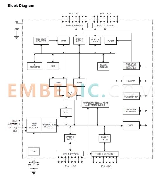
This is the Atmel official data sheet gives the internal structure of the schematic.
Central processor: including the operator ALU and control logic composition, which also includes a number of special function registers (SFR).
Memory: 51 series of microcontroller memory is used in the program memory and data memory completely separate Haver structure, the two have their own addressing methods, addressing space and control system. The size of the internal data memory and program memory is related to the model, and the external data memory and program memory can also be extended.
I/O port: The previous section has been introduced it is the basis for communication and operation of the chip and peripherals.
Timer / counter: Timer / counter is an important part of the 51 microcontroller, it is like a curriculum, when to let the chip to execute what program, of course, this is only part of its function, it can also output pulse signals, capture external pulses and so on.
Interrupt system: interrupt is simply to interrupt the long in the execution of the program to do another thing, just like we follow the schedule of classes, suddenly the weather forecast that the typhoon is coming, the school are going to be early dismissal. In the 51 microcontroller interrupt is to provide us with the opportunity to set some higher priority than the ordinary program has to deal with some time-sensitive tasks, after the execution of the interrupt event and then resume the execution of the normal program.
8051 series microcontrollers, including the enhanced 52 series, their appearance is basically universal, regardless of the production of that roughly can replace each other, of course, is the plug-in replacement plug-in, SMD replacement SMD! The following use the most basic version to introduce some of it is the pin distribution.
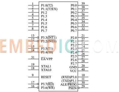
| Pins 1 to 8: | Port 1 (P1.0 to P1.7) - General-purpose I/O pins |
| Pins 9 to 16: | Port 3 (P3.0 to P3.7) - General-purpose I/O pins with alternate functions |
| Pins 17 to 24: | Port 2 (P2.0 to P2.7) - General-purpose I/O pins |
| Pins 25 to 32: | Port 0 (P0.0 to P0.7) - General-purpose I/O pins with additional functions |
| Pins 33 and 34: | XTAL1 and XTAL2 - Crystal oscillator connections for clock generation |
| Pin 40: | Supply voltage |
| Pin 20: | GND - Ground |
The 8051 microcontroller pinout includes 40 pins by function can be divided into four types:
1. Power pins: by VCC (+5V) and GND (ground) to provide power.
2. Clock signal pins: from XTAL0 and XTAL1 connected to the crystal to generate the system clock.
3. Control signal pins: RESET, ALE/PROG, PSEN and EA/VPP.
RESET is the reset signal input, triggering the chip reset when high.
ALE/PROG is the address latch allow signal, which is used as a control signal to latch the low 8-bit address by outputting a pulse signal when using external memory, it can also be used as a 51 MCU with on-chip EPROM to provide programming pulse input.
PSEN is the program memory allow output signal and is used as a chip select signal when using external memory.
EA /VPP is the external program memory address allow input control signal, which allows reading external EPROM when high and disables it when low. Its another function is to be used as input for curing programming voltage, this function is not used much, just understand it.
4. General-purpose input and output pins: ports P0~P3 can be used as input and output ports.
P0 port is an open-drain 8-bit quasi-bidirectional I/O port, external pull-up resistors are required to do the input.
Ports P1~P3 are quasi-bidirectional I/O ports with internal pull-up resistors, where each pin of port P3 also has a second function, such as serial port, external interrupt, timer calculator input, and external RAM read/write enable. In the enhanced chip P1.0 and P1.1 have the second function of timer 2 output signal terminal and timer 2 input capture terminal respectively.
Warm tip: These above information in addition to the textbook, the network has, more information can be obtained on the official website of the chip manufacturer or agent website. Here again, the importance of learning to get the chip manual, many textbooks or the author will not tell you the information in the chip manual may be able to find (now is a person can publish a book, and the person who published the book is not necessarily the actual application of what he wrote, the chip may not work in the same environment, even if you perform the same operation, the results may not be the same).
Atmel、 Silicon Labs、 NXP、 STMicroelectronics、 TI
Atmel AT89 series: Atmel (now Microchip) launched the AT89 series is a widely used 8051 microcontroller series, including AT89C51, AT89S51, AT89C52, AT89S52, etc.
Silicon Labs C8051 series: Silicon Labs' C8051 series is a series of high-performance 8051 microcontrollers with rich peripheral resources and integrated analog functions. Some of the common models include the C8051F series and the C8051F32x series.
NXP P89 series: The P89 series from NXP (formerly Philips) is a classic 8051 microcontroller series with a wide range of applications and market share. Some of the common models include P89V51RD2, P89C51RD2, etc.
STMicroelectronics STC89 series: STMicroelectronics' STC89 series is a series of low-power 8051 microcontrollers for many embedded applications. Some common models include STC89C52, STC89C516, STC89C58, etc.
TI MSP430 series: Although the MSP430 series is a low-power series of microcontrollers from TI (Texas Instruments), some of the models also use the 8051 instruction set architecture, such as MSP430F413, MSP430F415, etc.
In conclusion, the block diagram and pinout of the 8051 microcontroller provide a valuable insight into its internal structure and external connections. The well-defined architecture and pinout make it easier for developers to understand and utilize the capabilities of the 8051 microcontroller effectively.
Whether you are a professional embedded systems engineer or an electronics hobbyist, exploring the block diagram and pinout of the 8051 microcontroller opens up a world of possibilities for creating innovative and powerful applications. By leveraging the features and connectivity options offered by the 8051 microcontroller, you can design efficient and intelligent systems that cater to a wide range of applications.

Manufacturer: Texas Instruments
IC DSP FIX/FLOAT POINT 176HLQFP
Product Categories: DSP
Lifecycle:
RoHS:
Manufacturer: Texas Instruments
IC DGTL MEDIA PROCESSR 684FCBGA
Product Categories: DSP
Lifecycle:
RoHS:
Manufacturer: STMicroelectronics
IC MCU 8BIT 32KB FLASH 32LQFP
Product Categories: 8bit MCU
Lifecycle:
RoHS:
Manufacturer: Texas Instruments
IC DGTL MEDIA PROCESSR 1031FCBGA
Product Categories: DSP
Lifecycle:
RoHS:
Looking forward to your comment
Comment
1
2
3
4
5
6
 Popular Searches
8 Bit MCU, Flash, PIC16 Family PIC16F7XX Series Microcontrollers, 20 MHz, 7 KB, 192 Byte, 44 Pi...
EEPROM 2K 256 X 8 2.5V SERIAL EE IND
System-On-Modules - SOM RCM2200
32-bit Arm Cortex-A53 vision processor with ISP, powerful 3D GPU, dual APEX-2 vision accelerat...
IC MCU 8BIT 60KB FLASH 44QFP
DSP 20MHZ 44QFP
Product updates, events, and resources in your inbox


Smart System

Traffic Management

Security

Consumer Electronics

Wireless Technology

Robot

Internet of Things

Industrial Control


