Hello! Welcome to Embedic!
This article introduces a simple dual-use password doorbell circuit based on cd4069, which uses a doorbell button to identify the owner and the guest.
1. Working principle
The 220V alternating current is stepped down by a transformer, VD1-VD4 rectified, and C1 filtered to obtain +4.5V direct current voltage. IC1 is a six-not gate integrated circuit CD4069, and A.B.C.D.E is five of them.
Normally, the input terminals of gate A and gate B are connected to the power supply via resistor R1 and set high, so gate A and gate B output low level, gate C and gate D output high level, and gate E output low level . IC2 is a KD-156 type "Ding Dong and Birdsong" dual trigger dual tone doorbell dedicated integrated circuit. TG1 and TG2 are two pulse trigger terminals. TG1 positive pulse trigger is valid, and TG2 negative pulse trigger is valid.
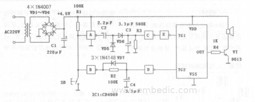
Door A and C2.C3.VD5.VD6.R3 form a high-pass filter, and door B, C4.VD7, R2 form a low-pass filter for detecting long and short pulse signals sent by the doorbell button. SB is the doorbell button. When SB is pressed for a long time, both door A and door B have input a negative long pulse.
Both gate A and gate B output high level, the high level output by gate B is charged to C4 through R2, because the charging time is longer. C4 can be charged to the flip level of gate D (about half of the power supply voltage value) , Gate D flips and outputs a low level, TG2 gets a negative pulse and is triggered, IC2 outputs a "Ding Dong" music signal from the OUT pin, which is amplified by the transistor VT and pushes the speaker to emit a "Ding Dong" sound with reverberation .
At the same time, the high level output from gate A is also charged to C2 and C3 via VD6, but due to the partial pressure of C2 and C3, one pulse is not enough to charge C3 to the flip level of gate C. Gate C does not flip, and TG1 gets Not trigger.
When SB is pressed continuously, both gate A and gate B output a series of positive short pulses. The series of short pulses output by gate A are detected by the voltage doubler of C2.C3 and VD5.VD6, so that the capacitor C3 is quickly charged to The gate C flips the level, and the gate C flips to output a low level. Gate E outputs a high level, TG1 is triggered, IC2 outputs a bird's song music signal from the OUT pin, which is amplified by the transistor VT, and pushes the speaker to emit a realistic bird's song.
However, a series of short pulses output from gate B slowly charge C4 through R2 when the pulse arrives, and quickly discharge C4 to the output terminal of gate B through VD7 when the pulse retreats. Therefore, C4 cannot be charged to the flip level of gate D. Gate D does not flip, and TG2 cannot be triggered.
From the above analysis, it can be seen that if you press SB quickly, the doorbell will make a chirp; if you press SB for a long time, or if you press SB quickly or slowly, the doorbell will make a “ding-dong” sound. When family members ring the doorbell, they can be identified as long as they follow the quick method of pressing the doorbell, because guests usually do not press the doorbell non-stop.
2. Component selection
Vl-V6 adopts 2SA970 and 2SC2240 complementary pairs of tubes. This pair of tubes has a charming tone and outstanding quality. The pairing requirements are not too harsh, and you can choose with a digital multimeter. It's just that the tube should be genuine, and the difference in multiples is not too great. V7 and V8 use mid-power pair tubes 2SB649 and 2SD669.
The pair of tubes has many disassembled goods, and the quality and symmetry are very good. The output tube uses 2SA1943, 2SC5200, the tone is warm and charming, which well reflects the tone characteristics of Toshiba tube. I think there is no obvious difference in tone between audiophile resistance and ordinary resistance.
This circuit uses ordinary 14/W five-color ring resistance. As long as the error is controlled below 2%. However, R17 to R20 need to be carefully selected, and imported goods are the best choice. The quality of Cl is very important. You can switch to a different fever product. You decide whether it is good or bad. The capacity of each power transformer should be above 250VA, and the radiator should be as large as possible to ensure safety.
3, production and debugging
Readers can design the printed circuit board according to the circuit diagram. The left and right sound channels are installed on the left and right sides of the chassis, and the power transformer is installed in the middle.
The sound channel separation is very good. Short-circuit the input terminal to ground, adjust W1 and W2 to the middle position, and short-circuit C7 with a wire to make the bias voltage of V7 and V8 zero. Turn on the power again, adjust W1 and W2 respectively to make the voltage between the collectors of V1, V3 and V2, V4 be zero.
At this time, the output midpoint voltage should be less than 20mV. Sometimes it is necessary to repeatedly adjust W1 and W2 until the midpoint potential of the output stage meets the requirements. Disconnect the C7 short-circuit wire and observe whether the power tube has abnormal heating.
Adjust W3 so that the voltage on each resistor of R17-R2O is about 0.183V, and the total quiescent current of the two pairs of output tubes is 0.78A. After one hour, repeat the above adjustment process once. After normal, you can add a sound source for trial listening.

IC MCU 16BIT 88KB FLASH 80TQFP

IC MCU 8BIT 1.5KB FLASH 20QFN

IC MCU 8BIT 8KB FLASH 20DIP

IC MCU 8BIT 1KB FLASH 8DIP
1
2
3
4
5
6


Product updates, events, and resources in your inbox


Smart System

Traffic Management

Security

Consumer Electronics

Wireless Technology

Robot

Internet of Things

Industrial Control