Hello! Welcome to Embedic!
Based on the RGMII timing widely used in Ethernet communication, the Xilinx-based 3-speed Ethernet timing analysis is different for different Xilinx series methods. When more than 2-way Ethernet communication is used, the MAC core of KU series FPGAs needs to be modified to support 2-way Ethernet and meet the timing requirements.
Mainly for the above three files to modify, the details can be opened in our supporting projects to read the code, the following figure is the first three Ethernet files
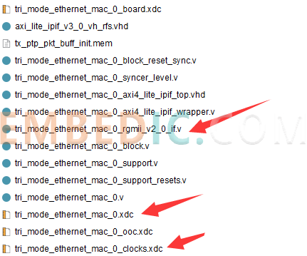
The following figure shows the first three Ethernet files. tri_mode_ethernet_mac_1_rgmii_v2_0_if.v file key part of the modification is as follows:
Send part of the code modification of odelay3, the original default code for rgmii_tx send timing adjustment is realized by cascading an idelay3 module, here to comment out the cascade idelay3 module, the default mode is "TIME" mode is the maximum delay adjustment of 1ns, modify the delay mode of the odelay3 module to "COUNT mode", so that every 1 tap adjustment represents a 1 ns delay. In this way, each adjustment of 1 tap represents 0.005ns, the maximum can be adjusted 512 tap, so that we can realize the maximum delay adjustment of more than 2ns.
//InstantiatetheOutputDelayprimitive(delayoutputby2ns).Inorderto
//achieve2ns,anODELAYiscascadedwithanIDELAYfromthebitslice
//immediatelybelowit.
ODELAYE3#(
.DELAY_VALUE(300),
.DELAY_FORMAT("COUNT"),//UnitsoftheDELAY_VALUE(COUNT,TIME)
.DELAY_TYPE("FIXED"),
//.CASCADE("MASTER"),
.REFCLK_FREQUENCY(333.333),
.SIM_DEVICE("ULTRASCALE")
)
delay_rgmii_tx_clk(
.ODATAIN(rgmii_txc_odelay),
.DATAOUT(rgmii_txc_obuf),
.CLK(1'b0),
.CE(1'b0),
.INC(1'b0),
.CNTVALUEIN(9'h0),
.CNTVALUEOUT(),
.LOAD(1'b0),
.RST(1'b0),
.CASC_IN(1'b0),
.CASC_RETURN(1'b0),
.CASC_OUT(),
.EN_VTC(1'b1)
);
/*
IDELAYE3#(
.DELAY_VALUE(320),
.DELAY_TYPE("FIXED"),
.CASCADE("SLAVE_END"),
.REFCLK_FREQUENCY(333.333),
.SIM_DEVICE("ULTRASCALE_PLUS")
)
delay_rgmii_tx_clk_casc(
.IDATAIN(1'b0),
.DATAOUT(delay_rgmii_tx_clk_casc_return),
.DATAIN(1'b0),
.CLK(1'b0),
.CE(1'b0),
.INC(1'b0),
.CNTVALUEIN(9'h0),
.CNTVALUEOUT(),
.LOAD(1'b0),
.RST(1'b0),
.CASC_IN(delay_rgmii_tx_clk_casc_out),
.CASC_RETURN(1'b0),
.CASC_OUT(),
.EN_VTC(1'b1)
);
*/
//---------------------------------------------------------------------------
//RGMIITransmitterLogic:
//driveTXsignalsthroughIOBsontoRGMIIinterface
//---------------------------------------------------------------------------
//Encodergmiictlsignal
assignrgmii_tx_ctl_int=tx_en_from_mac^tx_er_from_mac;
//InstantiateDoubleDataRateOutputcomponents.Then
//putdataandcontrolsignalsthroughODELAYcomponentsto
//providesimiliarnetdelaystothoseseenontheclksignal.
assigngmii_txd_falling=txd_from_mac[7:4];
genvari;
generatefor(i=0;i<4; i=i+1)
begin : txdata_out_bus
ODDRE1 #(
.SRVAL (1'b0)
)
rgmii_txd_out (
.Q (rgmii_txd_odelay[i]),
.C (tx_clk),
.D1 (txd_from_mac[i]),
.D2 (gmii_txd_falling[i]),
.SR (tx_reset)
);
ODELAYE3 #(
.DELAY_VALUE (0),
.DELAY_TYPE ("FIXED"),
.REFCLK_FREQUENCY (333.333),
.SIM_DEVICE ("ULTRASCALE")
)
delay_rgmii_txd (
.ODATAIN (rgmii_txd_odelay[i]),
.DATAOUT (rgmii_txd_obuf[i]),
.CLK (1'b0),
.CE (1'b0),
.INC (1'b0),
.CNTVALUEIN (9'h0),
.CNTVALUEOUT (),
.LOAD (1'b0),
.RST (1'b0),
.CASC_IN (1'b0),
.CASC_RETURN (1'b0),
.CASC_OUT (),
.EN_VTC (1'b1)
);
end
endgenerate
Similarly, receive part of idelay3 code modification, the original default for the "TIME" mode is a maximum of 1ns delay adjustment, modify the delay mode of idelay3 module for the "COUNT mode", so that each adjustment of 1 tap represents 0.005ns, the maximum can be adjusted to adjust the maximum of 512 taps, so that we can realize the maximum delay adjustment of more than 2ns!
IDELAYE3 #(
.DELAY_FORMAT ("COUNT"), // Units of the DELAY_VALUE (COUNT, TIME)
.DELAY_TYPE ("FIXED"),
.REFCLK_FREQUENCY (333.333),
.DELAY_VALUE (330), // Input delay value setting
.SIM_DEVICE ("ULTRASCALE")
)
delay_rgmii_rx_ctl (
.IDATAIN (rgmii_rx_ctl_ibuf),
.DATAOUT (rgmii_rx_ctl_delay),
.DATAIN (1'b0),
.CLK (1'b0),
.CE (1'b0),
.INC (1'b0),
.CNTVALUEIN (9'h0),
.CNTVALUEOUT (),
.LOAD (1'b0),
.RST (1'b0),
.CASC_IN (1'b0),
.CASC_RETURN (1'b0),
.CASC_OUT (),
.EN_VTC (1'b1)
);
genvar j;
generate for (j=0; j<4; j=j+1)
begin : rxdata_bus
IDELAYE3 #(
.DELAY_FORMAT ("COUNT"), // Units of the DELAY_VALUE (COUNT, TIME)
.DELAY_TYPE ("FIXED"),
.REFCLK_FREQUENCY (333.333),
.DELAY_VALUE (330), // Input delay value setting
.SIM_DEVICE ("ULTRASCALE")
)
delay_rgmii_rxd (
.IDATAIN (rgmii_rxd_ibuf[j]),
.DATAOUT (rgmii_rxd_delay[j]),
.DATAIN (1'b0),
.CLK (1'b0),
.CE (1'b0),
.INC (1'b0),
.CNTVALUEIN (9'h0),
.CNTVALUEOUT (),
.LOAD (1'b0),
.RST (1'b0),
.CASC_IN (1'b0),
.CASC_RETURN (1'b0),
.CASC_OUT (),
.EN_VTC (1'b1)
);
end
endgenerate
The following figure shows the three files of the second Ethernet, and their codes are slightly different due to the need to contribute part of the delay_ctr resources of the FPGA.
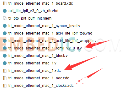
The modification method is the same as the first Ethernet modification method
ODELAYE3 #(
.DELAY_VALUE (300),
.DELAY_FORMAT ("COUNT"), // Units of the DELAY_VALUE (COUNT, TIME)
.DELAY_TYPE ("FIXED"),
//.CASCADE ("MASTER"),
.REFCLK_FREQUENCY (333.333),
.SIM_DEVICE ("ULTRASCALE")
)
delay_rgmii_tx_clk (
.ODATAIN (rgmii_txc_odelay),
.DATAOUT (rgmii_txc_obuf),
.CLK (1'b0),
.CE (1'b0),
.INC (1'b0),
.CNTVALUEIN (9'h0),
.CNTVALUEOUT (),
.LOAD (1'b0),
.RST (1'b0),
.CASC_IN (1'b0),
.CASC_RETURN (1'b0),
.CASC_OUT (),
.EN_VTC (1'b1)
);
/*
IDELAYE3 #(
.DELAY_VALUE (320),
.DELAY_TYPE ("FIXED"),
.CASCADE ("SLAVE_END"),
.REFCLK_FREQUENCY (333.333),
.SIM_DEVICE ("ULTRASCALE_PLUS")
)
delay_rgmii_tx_clk_casc (
.IDATAIN (1'b0),
.DATAOUT (delay_rgmii_tx_clk_casc_return),
.DATAIN (1'b0),
.CLK (1'b0),
.CE (1'b0),
.INC (1'b0),
.CNTVALUEIN (9'h0),
.CNTVALUEOUT (),
.LOAD (1'b0),
.RST (1'b0),
.CASC_IN (delay_rgmii_tx_clk_casc_out),
.CASC_RETURN (1'b0),
.CASC_OUT (),
.EN_VTC (1'b1)
);
*/
//---------------------------------------------------------------------------
// RGMII Transmitter Logic :
// drive TX signals through IOBs onto RGMII interface
//---------------------------------------------------------------------------
// Encode rgmii ctl signal
assign rgmii_tx_ctl_int = tx_en_from_mac ^ tx_er_from_mac;
// Instantiate Double Data Rate Output components. Then
// put data and control signals through ODELAY components to
// provide similiar net delays to those seen on the clk signal.
assign gmii_txd_falling = txd_from_mac[7:4];
genvar i;
generate for (i=0; i<4; i=i+1)
begin : txdata_out_bus
ODDRE1 #(
.SRVAL (1'b0)
)
rgmii_txd_out (
.Q (rgmii_txd_odelay),
.C (tx_clk),
.D1 (txd_from_mac),
.D2 (gmii_txd_falling),
.SR (tx_reset)
);
ODELAYE3 #(
.DELAY_VALUE (0),
.DELAY_TYPE ("FIXED"),
.REFCLK_FREQUENCY (333.333),
.SIM_DEVICE ("ULTRASCALE")
)
delay_rgmii_txd (
.ODATAIN (rgmii_txd_odelay),
.DATAOUT (rgmii_txd_obuf),
.CLK (1'b0),
.CE (1'b0),
.INC (1'b0),
.CNTVALUEIN (9'h0),
.CNTVALUEOUT (),
.LOAD (1'b0),
.RST (1'b0),
.CASC_IN (1'b0),
.CASC_RETURN (1'b0),
.CASC_OUT (),
.EN_VTC (1'b1)
);
end
endgenerate
Receiving part
IDELAYE3 #(
.DELAY_FORMAT ("COUNT"),
.DELAY_TYPE ("FIXED"),
.REFCLK_FREQUENCY (333.333),
.DELAY_VALUE (250), // Input delay value setting
.SIM_DEVICE ("ULTRASCALE")
)
delay_rgmii_rx_ctl (
.IDATAIN (rgmii_rx_ctl_ibuf),
.DATAOUT (rgmii_rx_ctl_delay),
.DATAIN (1'b0),
.CLK (1'b0),
.CE (1'b0),
.INC (1'b0),
.CNTVALUEIN (9'h0),
.CNTVALUEOUT (),
.LOAD (1'b0),
.RST (1'b0),
.CASC_IN (1'b0),
.CASC_RETURN (1'b0),
.CASC_OUT (),
.EN_VTC (1'b1)
);
genvar j;
generate for (j=0; j<4; j=j+1)
begin : rxdata_bus
IDELAYE3 #(
.DELAY_FORMAT ("COUNT"),
.DELAY_TYPE ("FIXED"),
.REFCLK_FREQUENCY (333.333),
.DELAY_VALUE (250), // Input delay value setting
.SIM_DEVICE ("ULTRASCALE")
)
delay_rgmii_rxd (
.IDATAIN (rgmii_rxd_ibuf[j]),
.DATAOUT (rgmii_rxd_delay[j]),
.DATAIN (1'b0),
.CLK (1'b0),
.CE (1'b0),
.INC (1'b0),
.CNTVALUEIN (9'h0),
.CNTVALUEOUT (),
.LOAD (1'b0),
.RST (1'b0),
.CASC_IN (1'b0),
.CASC_RETURN (1'b0),
.CASC_OUT (),
.EN_VTC (1'b1)
);
end
endgenerate
Above you can also see the difference in timing adjustments between the second Ethernet and the first Ethernet.
Since we finished the timing adjustment in tri_mode_ethernet_mac_1_rgmii_v2_0_if.v, we need to comment the following constraints
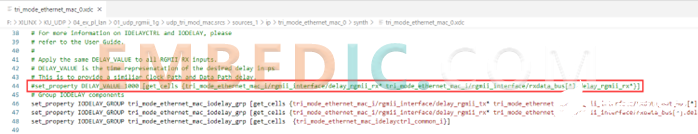
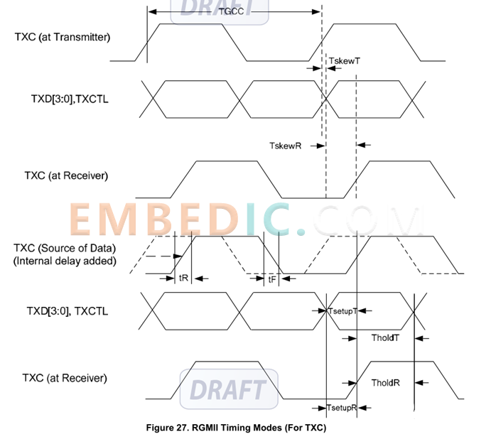
The timing constraints are partly related to the delay setting of the PHY on the hardware, the PHY Ethernet chip rx of the MILENC FPGA has a delay of 2ns and the tx does not have a delay of 2ns. Therefore, the rgmii_rx data is analyzed by the source synchronous center alignment, while the rgmii_tx data is analyzed by the source source step edge alignment. mLINK uses the RTL8211FD chip, and the key timing parameters are as follows:
Therefore the following timing constraints are given:
############################################################
# RX Clock period Constraints (per instance) #
############################################################
# Receiver clock period constraints: please do not relax
set rx_clk [get_clocks -of [get_ports rgmii_rxc]]
############################################################
# Obtain input clocks from top level XDC #
############################################################
set ip_gtx_clk [get_clocks -of_objects [get_ports gtx_clk]]
#
####
#######
##########
#############
#################
#BLOCK CONSTRAINTS
############################################################
# For Setup and Hold time analysis on RGMII inputs #
############################################################
# define a virtual clock to simplify the timing constraints
create_clock -name [current_instance .]_rgmii_rx_clk -period 8
set rgmii_rx_clk [current_instance .]_rgmii_rx_clk
# Identify RGMII Rx Pads only.
# This prevents setup/hold analysis being performed on false inputs,
# eg, the configuration_vector inputs.
set_input_delay -clock [get_clocks $rgmii_rx_clk] -max -1.5 [get_ports {rgmii_rxd
rgmii_rx_ctl}]
set_input_delay -clock [get_clocks $rgmii_rx_clk] -min -2.5 [get_ports {rgmii_rxd
rgmii_rx_ctl}]
set_input_delay -clock [get_clocks $rgmii_rx_clk] -clock_fall -max -1.5 -add_delay[get_ports {rgmii_rxd
rgmii_rx_ctl}]
set_input_delay -clock [get_clocks $rgmii_rx_clk] -clock_fall -min -2.5 -add_delay[get_ports {rgmii_rxd
rgmii_rx_ctl}]
set_false_path -rise_from [get_clocks $rgmii_rx_clk] -fall_to $rx_clk -setup
set_false_path -fall_from [get_clocks $rgmii_rx_clk] -rise_to $rx_clk -setup
set_false_path -rise_from [get_clocks $rgmii_rx_clk] -rise_to $rx_clk -hold
set_false_path -fall_from [get_clocks $rgmii_rx_clk] -fall_to $rx_clk -hold
set_multicycle_path -from [get_clocks $rgmii_rx_clk] -to $rx_clk -setup 0
set_multicycle_path -from [get_clocks $rgmii_rx_clk] -to $rx_clk -hold -1
############################################################
# For Setup and Hold time analysis on RGMII outputs #
############################################################
create_generated_clock -name [current_instance .]_rgmii_tx_clk -divide_by 1 -source[get_pins {tri_mode_ethernet_mac_i/rgmii_interface/rgmii_txc_ddr/C}] [get_ports rgmii_txc]
set rgmii_tx_clk [current_instance .]_rgmii_tx_clk
set_output_delay -0.5 -max -clock [get_clocks $rgmii_tx_clk] [get_ports {rgmii_txd
rgmii_tx_ctl}]
set_output_delay -1.2 -min -clock [get_clocks $rgmii_tx_clk] [get_ports {rgmii_txd
rgmii_tx_ctl}]
set_output_delay -0.5 -max -clock [get_clocks $rgmii_tx_clk] [get_ports {rgmii_txd
rgmii_tx_ctl}] -clock_fall -add_delay
set_output_delay -1.2 -min -clock [get_clocks $rgmii_tx_clk] [get_ports {rgmii_txd
rgmii_tx_ctl}] -clock_fall -add_delay
set_false_path -rise_from $ip_gtx_clk -fall_to [get_clocks $rgmii_tx_clk] -setup
set_false_path -fall_from $ip_gtx_clk -rise_to [get_clocks $rgmii_tx_clk] -setup
set_false_path -rise_from $ip_gtx_clk -rise_to [get_clocks $rgmii_tx_clk] -hold
set_false_path -fall_from $ip_gtx_clk -fall_to [get_clocks $rgmii_tx_clk] -hold
set_multicycle_path -from $ip_gtx_clk -to [get_clocks $rgmii_tx_clk] 0 -setup
set_multicycle_path -from $ip_gtx_clk -to [get_clocks $rgmii_tx_clk] -1 -hold

Manufacturer: Texas Instruments
IC DGTL MEDIA PROCESSR 1031FCBGA
Product Categories: DSP
Lifecycle:
RoHS:
Manufacturer: Texas Instruments
IC DSP ARM SOC BGA
Product Categories: SOC
Lifecycle:
RoHS:
Manufacturer: Texas Instruments
IC DSP FIX/FLOAT POINT 176HLQFP
Product Categories: DSP
Lifecycle:
RoHS:
Manufacturer: Texas Instruments
IC DGTL MEDIA PROCESSR 684FCBGA
Product Categories: DSP
Lifecycle:
RoHS:
Looking forward to your comment
Comment
1
2
3
4
5
6
 Popular Searches
8 Bit MCU, Flash, PIC16 Family PIC16F7XX Series Microcontrollers, 20 MHz, 7 KB, 192 Byte, 44 Pi...
EEPROM 2K 256 X 8 2.5V SERIAL EE IND
System-On-Modules - SOM RCM2200
32-bit Arm Cortex-A53 vision processor with ISP, powerful 3D GPU, dual APEX-2 vision accelerat...
IC MCU 8BIT 60KB FLASH 44QFP
DSP 20MHZ 44QFP
Product updates, events, and resources in your inbox


Smart System

Traffic Management

Security

Consumer Electronics

Wireless Technology

Robot

Internet of Things

Industrial Control


