Hello! Welcome to Embedic!
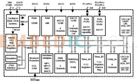
Texas Instruments (TI) MSP430TM series microcontroller is a streamlined instruction set processor (Reduced Instruction Set Computing, RISC) based 16-bit mixed-signal processor. The chip has an integrated analog-to-digital converter (ADC) and digital-to-analog converter (DAC), which makes it capable of receiving and outputting not only digital signals, but also analog signals, hence the name mixed-signal processor. The block diagram of the MSP430 family of microcontrollers is shown in the figure.
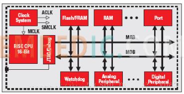
The CPU module in the ti launchpad MSP430 family of microcontrollers, the "RISC CPU 16-Bit" module in the diagram above, is connected to the program memory module, data memory module, and various external device modules via the Memory Address Bus (MAB) and Memory Data Bus (MDB), and uses a unified CPU instruction and addressing mode.
If programming in assembly language, developers need to understand the internal registers, various addressing modes and assembly instructions of the CPU; if programming in C language, these contents do not need much attention, and the use of registers and the selection of addressing modes will be handled by the compiler system. This book adopts C language to realize the development of application system.
The "Flash/FRAM" module is used as program memory, the "RAM" module is used as data memory, and the "Port" module indicates the input/output pins of the chip. MSP430 family of microcontrollers has a variety of chip models, the same model chip also has a variety of package types, a total of more than 400. In all these models of chips, the chip internal program memory storage capacity from the smallest 0.5KB, to the largest 256KB; data memory storage capacity from the smallest 128B, to the largest 18KB; input / output pin number from 14 to 113. Different chip internal resource configurations are used to meet the different application requirements of different users in terms of functionality and cost.
Digital peripheral modules include LCD drivers, timers/counters, parallel digital input/output ports and serial digital input/output ports. Analog peripheral modules include analog/digital converters, digital/analog converters, comparators, operational amplifiers, etc. Note that not every MSP430 microcontroller chip can provide the functions of all these peripheral modules, users need to choose the appropriate chip model according to the needs of the application system.
Watchdog timer, commonly known as the watchdog "Watchdog", used to monitor the working status of the microcontroller. It will force the system to reset when there is an abnormal program operation.
Module "JTAG/Debug" is used to support the download and debugging of user programs, the JTAG interface establishes a link between the computer used for development and the MSP430 microcontroller chip. all models of MSP430 series microcontrollers support programming of program memory through the JTAG interface. The MSP430 launchpad family of microcontrollers contains internal on-chip debug logic, which supports both high-precision analog debug and full-speed operation debug. Some models of the chip also support a 2-wire interface called "Spy-Bi-Wire", which also supports the download and debugging of user programs.
Ti MSP430 series microcontroller's most important feature is low power consumption. To reduce power consumption, the chip is designed for a flexible clock system, a variety of low-power operating modes, instant wake-up and intelligent external device module.
Clock module "Clock System" is used to generate the MSP430 arduino series microcontroller work required for a variety of clock signals. The module can work under the support of multiple clock sources, both the need to add external crystals to obtain high frequency stability of the clock source, there is no need to add any external devices internal clock source. The operating state and frequency of the clock module can be controlled by the user program, which allows the microcontroller to use a low frequency clock signal in the waiting state, or even turn off the clock circuit to reduce the energy consumption of the system; in the operating state, a high frequency clock signal is used to speed up the processing of the signal. The user program can select the clock source, and control the clock circuit operating state and clock frequency, which is one of the MSP430 series microcontroller features.
Currently, Texas Instruments (TI) produces the MSP430 series of microcontrollers include the following subseries. MSP430x1xx sub-series with instruction execution speed up to 8MIPS, MSP430x2xx sub-series with instruction execution speed up to 16MIPS, MSP430x4xx sub-series capable of directly driving LCD displays, MSP430x5xx sub-series with instruction execution speed up to 25MIPS, and MSP430x5xx sub-series with instruction execution speed up to 25MIPS and capable of directly driving LCD displays. and the MSP430x6xx subfamily, which can directly drive LCD displays. These subseries include hundreds of chips with different logic resources and package types, and readers can find information on the Texas Instruments website.
The MSP430x2xx subfamily of microcontrollers can also be subdivided into the MSP430G2xx, MSP430F2xx and MSP430AFE2xx subfamilies. This article only introduces the MSP430G2231 and MSP430F2619 chips of these 2 models. Hardware is the basis for software development, hardware is also the object of software control, only to understand the hardware situation in order to choose the right model of chip for the application system, and the successful completion of software development.
Chip MSP430G2231 is one of the many chips supported in the LaunchPad (MSP-ESP430G2) development kit provided by Texas Instruments (TI) to universities, in addition, MSP430G2231 chip has a double inline type package, easy to assemble application circuits on the breadboard. Assemble their own application circuit is very important for beginners, even if the microcontroller is used to write programs to achieve the function of the circuit, but the hardware is the basis for the software, but also the software control object. Only with an in-depth understanding of the hardware circuit can you write a good program. Assembling the circuit is an effective way to understand the hardware circuit. one of the shortcomings of the MSP430G2xx family of chips is that it does not support external high resonant frequency crystal clock source, it only supports a 32.768kHz clock crystal. Chip MSP430F2619 supports external crystal clock sources up to 16MHz frequency, but of course also supports internal clock sources without adding any external devices. In addition, the chip MSP430F2619 has a wider variety of peripheral modules and a larger number of logic resources than the chip MSP430G2231.
14-pin dual inline type package MSP430G2231 chip pinout diagram is shown in the figure.
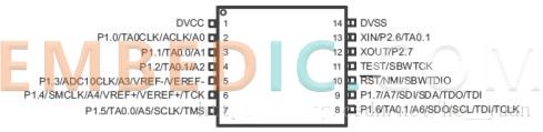
The MSP430G2231 chip has a dual inline type package, which is very convenient for beginners because the dual inline type package is easy to assemble the application circuit on the breadboard. The ability to observe the work of their own completed design, assembly of the circuit will enable designers to immediately experience the joy of success and enhance the interest in learning. Having an interest in what you are doing is an important condition for doing a good job. At the same time, theory and practice is also a very important method of work and learning.
The minimum system circuit diagram based on MSP430G2231 chip is shown in the figure below.
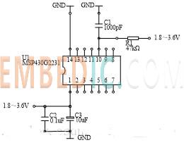
MSP430G2231 chip has 14 pins. Pin DVCC (pin 1) is the power supply pin, and pin DVSS (pin 14) is the ground pin. The power supply voltage range is 1.8 to 3.6 V. When using a breadboard to assemble the application circuit, the power supply and ground can be easily connected nearby, so multiple power terminals and ground terminals appear in the circuit diagram, and these endpoints can be completed by the reader to connect to the power supply and ground. 2 capacitors, C2 and C3, placed next to the power supply pin (pin 1) of the MSP430G2231 chip, are used for filtering of the power supply.
MSP430G2231 chip pin 10 is the reset pin (). The purpose of the reset is to enable the microcontroller to start operating from an agreed operating state. the MSP430 family of chips will enter a reset state whenever the reset pin is logic low when connected to power. A very simple reset circuit is given, consisting of only 1 resistor and 1 capacitor, R1 and C1. When the MSP430 MCU system is powered up, the reset pin goes low because the voltage on capacitor C1 cannot change abruptly, causing the microcontroller to enter a reset state. As capacitor C1 charges, the potential of the reset pin gradually rises, and when the value of the potential corresponding to the logic high is reached, the microcontroller will exit the reset state and enter the normal operating state.
MSP430G2231 chip clock module "Clock System" can be driven by the following three clock sources, using a frequency of 32768Hz external crystal resonator oscillator, frequency of about 12kHz internal low-power oscillator and internal digital control oscillator ( Digitally Controlled Oscillator (DCO). To use the crystal oscillator, a crystal resonator with a resonant frequency of 32768Hz is placed between pin XIN (pin 13) and pin XOUT (pin 12), and each of the two pins is then grounded through a 12pF capacitor. Using the internal low-power oscillator and the internal DCO does not require any external devices to be added, and the DCO operating frequency can be adjusted by the user program. The disadvantage of using an internal clock source is that the clock frequency is not as stable and accurate as an oscillator using an external crystal resonator. The circuit shown in the figure uses an on-chip clock source to simplify the circuit composition.
The MSP430G2553 launchpad family of chips automatically selects a digital control oscillator (DCO) as the clock source after reset, with a default clock frequency of approximately 1 MHz. it is recommended that beginners use the chip's internal DCO, which reduces the number of wires and eliminates the need to program the clock module.
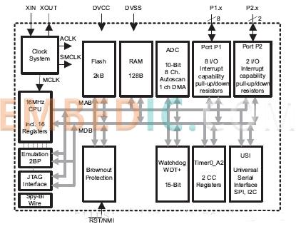
Texas Instruments (TI) produced 64-pin PM package form the MSP430F2619 chip pin arrangement and functional block diagram are shown below.
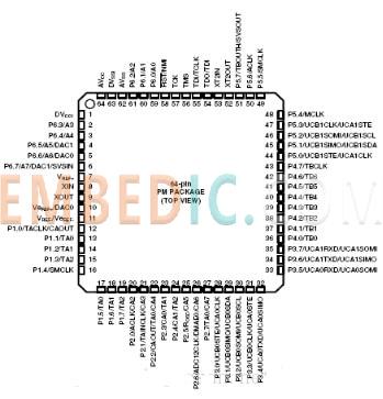
MSP430G2231 chip has a two-row inline package form, cheap, suitable for beginners, but the chip has less internal logic resources. MSP430F2619 chip only table-mounted package form, must be designed specifically for it printed circuit board, together with the chip itself, making the use of higher costs, but the chip has a wealth of internal logic resources.
MSP430F2619 chip uses 2 groups of power supply pins. The first group, DVCC and DVSS, for the digital circuit part of the power supply pins. Group 2, AVCC and AVSS, for the analog circuit part of the power supply pins. The purpose of dividing into two parts is to avoid the influence of the operation of the digital circuit on the stability of the analog circuit power supply.
The system clock module "Clock System" is capable of connecting two types of resonant crystals, one with a lower resonant frequency and the other with a higher resonant frequency. The maximum resonant frequency of the crystal is 16 MHz, and the high clock frequency supports the fast signal processing speed of the chip. Using a crystal resonator-based clock signal source, the msp430 datasheet has much higher frequency stability than using the chip's internal clock signal source.
MSP430 F2619 chip has 120kB of Flash program memory, 4kB of RAM data memory.
For analog signal interface, MSP430F2619 chip has analog/digital conversion and digital/analog conversion capability. The chip's internal analog/digital converter has 12-bit resolution with 8 independent channels, each of which can be set by software to connect to the chip's pins. The chip's internal digital/analog converter also has 12-bit resolution with 2 independent channels, each of which is also set to connect to the chip's pins via software.
For digital signal interfaces, the MSP430F169 chip provides parallel and serial digital input/output ports. The former includes 6 ports with 8 bits, P1 to P6 ports; the latter has 2, both of which are capable of operating in UART, SPI, or I2C modes of operation. Each type of port can be set to connect to the chip's pins via user software.
The chip also contains two 16-bit timers with capture/compare functionality, analog voltage comparator, watchdog "Watchdog" circuit, hardware multiplier and other circuits. ESP430G2) development kit using "Spy-Bi-Wire" 2-wire interface, so this development kit can not be used to achieve the MSP430F2619 chip programming / debugging.
Texas Instruments (TI) MSP430 series microcontroller (MCU) chip has an internal integrated analog/digital converter (ADC) and digital/analog signal converter (DAC), which makes it able to receive and output not only digital signals, but also analog signals, so called mixed-signal processors.
MSP430 microcontroller basics series of microcontrollers is the most important feature of energy saving, for which the series of chips have user-programmable clock circuit and system operating mode. In order to meet the needs of different applications, TI offers a variety of models of chips, which have different prices, different functional module composition, different logic resources and different package forms.
Manufacturer: Texas Instruments
IC DSP FIXED-POINT 688FCBGA
Product Categories: DSP
Lifecycle:
RoHS:
Manufacturer: Texas Instruments
IC MCU 16BIT 2KB FLASH 14TSSOP
Product Categories: 16bit MCU
Lifecycle:
RoHS:
Manufacturer: Microchip
IC MCU 8BIT 7KB FLASH 28SSOP
Product Categories: 8bit MCU
Lifecycle:
RoHS:
Manufacturer: Analog Devices
IC DSP 16/32B 400MHZ LP 176LQFP
Product Categories: DSP
Lifecycle:
RoHS:
Looking forward to your comment
Comment
1
2
3
4
5
6
 Popular Searches
8 Bit MCU, Flash, PIC16 Family PIC16F7XX Series Microcontrollers, 20 MHz, 7 KB, 192 Byte, 44 Pi...
EEPROM 2K 256 X 8 2.5V SERIAL EE IND
System-On-Modules - SOM RCM2200
32-bit Arm Cortex-A53 vision processor with ISP, powerful 3D GPU, dual APEX-2 vision accelerat...
IC MCU 8BIT 60KB FLASH 44QFP
DSP 20MHZ 44QFP
Product updates, events, and resources in your inbox


Smart System

Traffic Management

Security

Consumer Electronics

Wireless Technology

Robot

Internet of Things

Industrial Control


